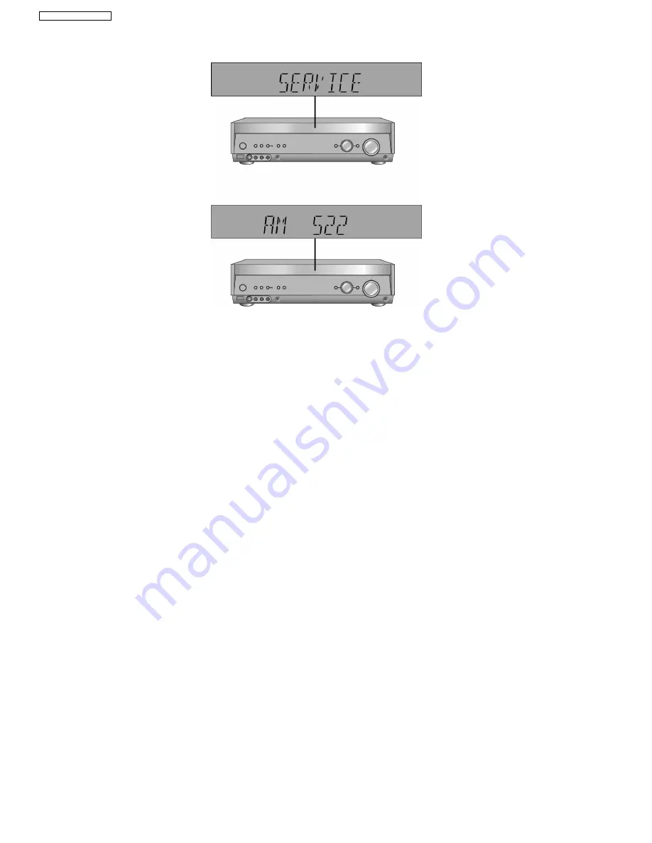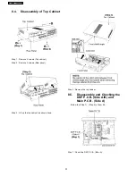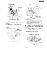
2. The message, [SERVICE] appears on the display for three seconds, and then it will display the following. Refer to Fig. 6.2.
Fig. 6.2
3. When the [SPEAKER A] button is pressed, the current program filing number [M003 NO] appears. The *** digit indicates the
ROM checksum used for ROM collection, and if the unit is not loaded with ROM, "NO" appears.
When the [SPEAKER B] button is pressed, the sub micro computer program filing number [S001 NO] appears. The *** digit
indicates the ROM checksum used for ROM collection, and if the unit is not loaded with ROM, "NO" appears.
6.7. Analog 6.1 CH Output Check Method
When the [SUBWOOFER] button on the remote controller, the function is switched to "Input Inspection Mode", which output analog
input signals at L channel of VCR analog input to all channels.
6.8. Returning to Normal Display
Press the [POWER] button on the unit to exit the function. The power is turned off.
6.9. Activating Self Diagnosis Function (Doctor Mode)
This mode can be used during servicing.
1. Plug the AC adapter to the power source. Press and hold down the [MENU-SETUP, RETURN] button and the [SPEAKERS A]
button, and then press the [POWER] button at the same time.
2. Initialize all the setting and set the frequency “93.40MHz” to Tuner.
The message, “_DOCTOR_” appears on the display for three seconds, and then it will display the following. Refer to Fig. 6.3.
20
SA-XR58E / SA-XR58EG
Summary of Contents for SA-XR58E
Page 9: ...5 Operating Instructions Procedures 5 1 Remote Control Operation 9 SA XR58E SA XR58EG ...
Page 10: ...5 2 Main Unit Operation 10 SA XR58E SA XR58EG ...
Page 11: ...5 3 Main Unit connections SA XR58 5 3 1 HDMI connection 11 SA XR58E SA XR58EG ...
Page 12: ...5 3 2 Video connection 12 SA XR58E SA XR58EG ...
Page 13: ...13 SA XR58E SA XR58EG ...
Page 14: ...5 3 3 Audio connection 14 SA XR58E SA XR58EG ...
Page 15: ...15 SA XR58E SA XR58EG ...
Page 16: ...5 3 4 Connection with other equipments 16 SA XR58E SA XR58EG ...
Page 17: ...5 3 5 Tuner Antenna Connection Power 17 SA XR58E SA XR58EG ...
Page 18: ...5 3 6 Headphone connection 18 SA XR58E SA XR58EG ...
Page 29: ...8 3 Main Parts Location Diagram 29 SA XR58E SA XR58EG ...
Page 58: ...SA XR58E SA XR58EG 58 ...
Page 68: ...68 SA XR58E SA XR58EG ...
Page 96: ...SA XR58E SA XR58EG 96 ...
Page 106: ...SA XR58E SA XR58EG 106 ...
Page 110: ...110 SA XR58E SA XR58EG ...
Page 111: ...17 Exploded Views 17 1 Cabinet Parts Location SA XR58E SA XR58EG 111 ...
Page 112: ...SA XR58E SA XR58EG 112 ...
Page 113: ...17 2 Packaging SA XR58E SA XR58EG 113 ...
Page 114: ...SA XR58E SA XR58EG 114 ...


