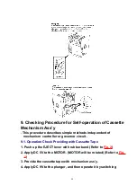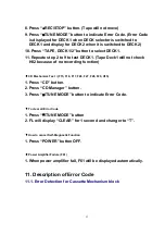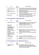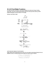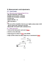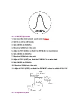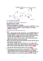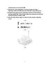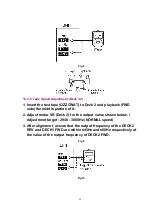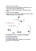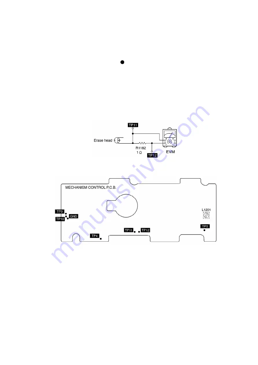
1. Set the unit to “AUX” position.
2. Insert the Normal blank tape (QZZCRA) into DECK2 and set the
unit to “REC” mode (use “ REC/STOP” key).
3. Measure and make sure that the output is within the standard
value.
4. Insert the CrO2 tape (QZZCRX).
5. Repeat step 2 and 3. / Standard value (Normal) : more than 100mV
/ Standard value (CrO2) : more than 150mV
Fig.13
13.2.7. Adjustment Point
Fig.14
14. Illustration of ICs, Transistors and Diodes
15. Schematic Diagram
15.1. Schematic Diagram Notes
- This schematic diagram may be modified at any time with the
development of new technology.
Notes:
62
Summary of Contents for SAAK58 - MINI HES W/CD
Page 7: ...6 Location of Controls 7 ...
Page 8: ...7 Location of Controls for Remote Control Transmitter 8 ...
Page 10: ...8 1 Checking for the main P C B 10 ...
Page 12: ...12 ...
Page 13: ...13 ...
Page 21: ...21 ...
Page 22: ...22 ...
Page 23: ...23 ...
Page 25: ...item 8 2 2 25 ...
Page 26: ...26 ...
Page 27: ...27 ...
Page 29: ...29 ...
Page 30: ...30 ...
Page 31: ...31 ...
Page 32: ...32 ...
Page 33: ...33 ...
Page 34: ...34 ...
Page 35: ...35 ...
Page 36: ...36 ...
Page 37: ...37 ...
Page 39: ...39 ...
Page 41: ...41 ...
Page 43: ...43 ...
Page 44: ...44 ...
Page 45: ...45 ...
Page 47: ...8 12 Measure for tape trouble Follow the Step 1 Step 3 of item 8 1 47 ...
Page 82: ...S638 EVQ21405R SW POWER 1 M 82 ...
Page 86: ...A4 RSA0006 J FM ANTENNA 1 M 86 ...
Page 107: ...107 ...
Page 108: ...23 Mechanism Parts Location 108 ...
Page 109: ...109 ...
Page 110: ...24 CD Mechanism Parts Location 110 ...
Page 111: ...25 Packaging 111 ...
Page 112: ...Printed in Japan M000500000MT 112 ...
Page 141: ......
Page 142: ......

