background image

18

RQT9882

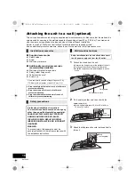
Attaching the unit to a wall (optional)

This unit can be wall mounted using the supplied wall mount brackets, etc. Make sure that the wall and the 
screws used for securing to the wall are capable of supporting at least 33 k

g

 (72.8 lbs). The screws and 

other items are not supplied as the type and size will vary with each installation.

Refer to step 5 of “Wall mount instructions” for details about the required screws.

As an additional protective measure, attach the unit to the wall with the fall prevention cord.

Supplied accessories

1 Safety holder

1 Screw

2 Wall mount brackets

Additionally required accessories 
(commercially available)

4 Wall mount bracket fixing screws

1 Safety holder fixing screw

1 Fall prevention cord*

1 Screw eye

* Use a cord that is capable of supporting over 33 k

g


(72.8 lbs) (with a diameter of about 1.5 mm (

1

/

16

q

)).

1

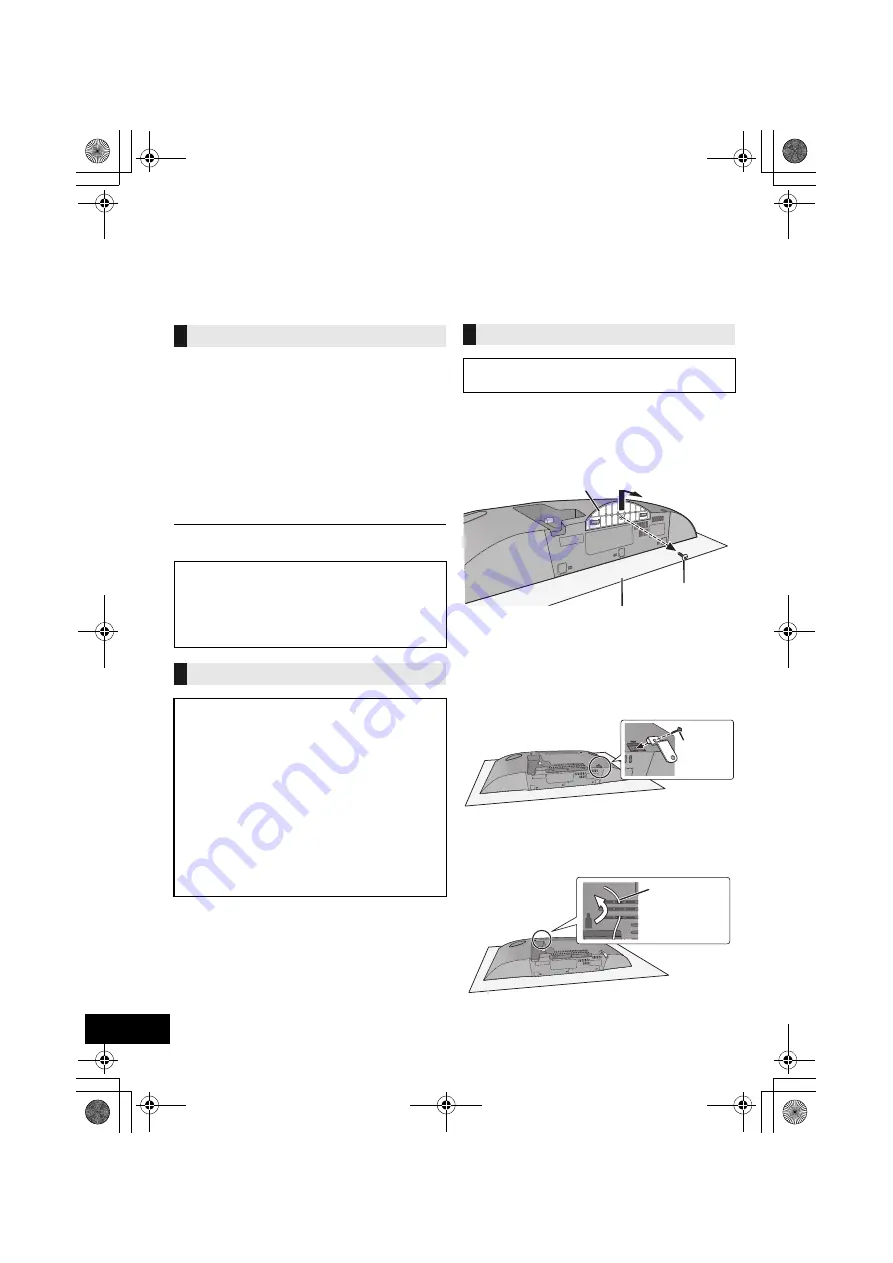
Detach the stand from the unit.

Unscrew the fixing screw at the bottom of the unit.

Gently pull the stand off the unit as illustrated.

Keep the removed screw and the stand in a safe 
place.

2

Fix the safety holder onto the unit with the 
screw (supplied).

Screw tightening torque: 50 N

0

cm (0.4 lbf

0

ft) to 

70 N

0

cm (0.5 lbf

0

ft).

3

Attach the fall prevention cord (not supplied) to 
this unit.

Installation accessories

Keep the safety holder out of reach of children to 
prevent swallowing.

Keep the screws out of reach of children to 
prevent swallowing.

Keep the wall mount brackets out of reach of 
children to prevent swallowing.

Safety precautions

Professional installation is required.
The installation should never be done by any 
other than a qualified installation specialist.
PANASONIC DISCLAIMS ANY PROPERTY 
DAMAGE AND/OR SERIOUS INJURY, 
INCLUDING DEATH RESULTING FROM 
IMPROPER INSTALLATION OR INCORRECT 
HANDLING.

WARNING:

To prevent injury, this apparatus must be 
securely attached to the wall in accordance with 
the installation instructions.

Wall mount instructions

Before installation, turn the unit off and disconnect 
the AC power supply cord from the AC outlet.

Stand

Fixing screw

Soft blanket or cloth

Screw
(supplied)

Cord 
(not supplied)

SC-HC39_PPC~RQT9882_mst.book  18 ページ  2014年3月26日 水曜日 午後2時12分

Summary of Contents for SC-C39

Page 1: ...mers only Compact Stereo System Model No SC HC39 Included Installation Instructions l p 2 and 18 19 The installation work should be done by a qualified installation specialist Before commencing work carefully read these installation instructions and the operating instructions to ensure that installation is performed correctly Please keep these instructions You may need them when maintaining or mov...

Page 2: ...ave fallen into the apparatus the apparatus has been exposed to rain or moisture does not operate normally or has been dropped Unit To reduce the risk of fire electric shock or product damage Do not expose this unit to rain moisture dripping or splashing Do not place objects filled with liquids such as vases on this unit Use only the recommended accessories Do not remove covers Do not repair this ...

Page 3: ...ES ONLY IN THE U S A FCC Note This equipment has been tested and found to comply with the limits for a Class B digital device pursuant to Part 15 of the FCC Rules These limits are designed to provide reasonable protection against harmful interference in a residential installation This equipment generates uses and can radiate radio frequency energy and if not installed and used in accordance with t...

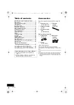
Page 4: ...ons in this Owner s Manual Pages to be referred to are indicated as l p Unless otherwise indicated operations are described using the remote control Check the supplied accessories before using this unit 1 Remote control N2QAYB000949 1 Battery for remote control 1 AC power supply cord K2CB2CB00022 1 FM indoor antenna RSAX0002 Wall mounting accessories 1 Safety holder RSC1266 1 Screw XTB3i8JFJK 2 Wa...

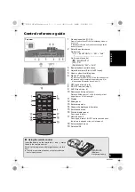
Page 5: ... DC OUT terminal l p 7 9 AUX IN jack l p 6 10 Remote control signal sensor Distance Within approx 7 m 23 ft directly in front Angle Approx 30o left and right 11 Display 12 Sliding door 13 Enter setup menu 14 Change the displayed information 15 Enter sound menu 16 Dim the display panel Press again to cancel 17 Mute the sound Press again to cancel MUTE is also canceled when the volume is adjusted or...

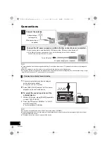
Page 6: ...UT LEVEL 2 Press 3 4 to select NORMAL or HIGH and then press OK The factory default is NORMAL To improve sound distortion when HIGH is selected select NORMAL Switch the equalizer off or turn the volume of the external device down to reduce the input signal High level of input signal will distort the sound For details refer to the owner s manual of the device Connect an external music device 1 Adhe...

Page 7: ...ual of your device before use Do not connect a device with a rated value higher than 5 V 1 5 A to this unit To check if charging is complete look at the screen of the connected device etc Once fully charged remove the USB cable from the DC OUT terminal To continue charging during standby mode make sure the device has started charging before turning the unit to standby mode When charging a depleted...

Page 8: ...mmunication compatible Bluetooth device on the unit you can complete all preparations from registering a Bluetooth device to establishing a connection Preparation Turn on the NFC feature of the device An Android device lower than version 4 1 requires the installation of the App Panasonic Music Streaming free of charge 1 Enter Panasonic Music Streaming in the search box of Google PlayTM to search a...

Page 9: ...nput level setting Preparation Connect a Bluetooth device 1 Press PLAY MENU repeatedly to select INPUT LEVEL 2 Press 3 4 to select the level and then press OK LEVEL 0 LEVEL i1 LEVEL i2 J Select LEVEL 0 if the sound is distorted The factory default is LEVEL 0 1 While a Bluetooth device is connected Press PLAY MENU repeatedly to select DISCONNECT 2 Press 3 4 to select OK YES and then press OK You ca...

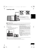
Page 10: ...4 to select the setting and then press OK During random play you cannot skip to the previous track The mode is canceled when you open the sliding door CD CD audio in CD DA format Bluetooth Connected Bluetooth device Basic controls CD Bluetooth Play Press 1 Stop Press Pause Press 1 Press again to restart play Skip Press 6 or 5 9 to skip track Search During play or pause press and hold 6 or 5 9 Play...

Page 11: ...ress 3 4 to select MANUAL and then press OK 3 Press 6 or 5 9 to tune to the required station To start automatic tuning press and hold 6 or 5 9 until the frequency starts scrolling Tuning stops when a station is found To preset the channel 4 While listening to the radio broadcast press OK 5 Press 3 4 to select the channel and then press OK To improve FM sound quality 1 While receiving FM broadcasts...

Page 12: ...MER SET 3 Press 3 4 to select SET and then press OK F is displayed To turn the timer off select OFF 4 Press Í to turn the unit to standby mode To display the timer settings press SETUP repeatedly to select TIMER ADJ and then press OK once The music source and volume will also be displayed if the timer is turned on During standby if the timer is turned on press DISPLAY twice to display the settings...

Page 13: ...sponds to the supplied remote control change the remote control code 1 Press CD to select CD 2 While pressing and holding SELECTOR on the unit press and hold CD on the remote control until the unit s display shows REMOTE 2 3 Press and hold OK and CD on the remote control for at least 4 seconds To change the mode back to REMOTE 1 press CD to select CD and then repeat the step 2 and 3 but replace CD...

Page 14: ... again Pairing cannot be completed Check the Bluetooth device condition The device cannot be connected The pairing of the device was unsuccessful or the registration has been replaced Try re pairing the device l p 8 This unit might be connected to a different device Disconnect the other device and try re pairing the device l p 8 The device is connected but audio cannot be heard through this unit F...

Page 15: ... set Adjust the clock accordingly ADJUST TIMER Play timer is not set Adjust the play timer accordingly AUTO OFF The unit has been left unused for about 20 minutes and will shut down within a minute Press any button to cancel it DIMMER Appears 10 seconds after the volume is turned to 0 ERROR Incorrect operation is performed Read the instructions and try again F stands for a number There is a proble...

Page 16: ...b if it is extremely dirty You cannot use a CD type lens cleaner Do not leave the sliding door open for prolonged periods of time This will cause the lens to get dirty Be careful not to touch the lens with your fingers Clean discs Wipe with a damp cloth and then wipe dry Disc handling precautions Handle discs by the edges to avoid inadvertent scratches or fingerprints on the disc Do not attach lab...

Page 17: ...ssibly not sufficient Transmit data wirelessly to this system with caution This system cannot transmit data to a Bluetooth device Range of use Use this device at a maximum range of 10 m 33 ft The range can decrease depending on the environment obstacles or interference Interference from other devices This system may not function properly and troubles such as noise and sound jumps may arise due to ...

Page 18: ...as illustrated Keep the removed screw and the stand in a safe place 2 Fix the safety holder onto the unit with the screw supplied Screw tightening torque 50 N0cm 0 4 lbf0ft to 70 N0cm 0 5 lbf0ft 3 Attach the fall prevention cord not supplied to this unit Installation accessories Keep the safety holder out of reach of children to prevent swallowing Keep the screws out of reach of children to preven...

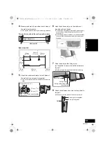
Page 19: ...t release your hands carefully to confirm the unit sits securely on the wall mount brackets 7 Drive the safety holder fixing screw not supplied to secure the safety holder onto the wall Refer to step 5 for requirements before screwing 8 Attach the fall prevention cord not supplied to the wall Make sure that the slack of the cord is minimal 204 mm 8q 13 mm 1 2q 300 mm 11 13 16q 500 mm 19 11 16q 75 ...

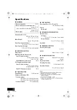
Page 20: ...h driven 20 W per channel 8 1 kHz 10 THD Total RMS Stereo mode power 40 W FTC Output Power Stereo mode Front Ch both ch driven 15 W per channel 8 20 Hz to 20 kHz 1 THD Total FTC Stereo mode power 30 W TUNER SECTION Preset Memory FM 30 stations Frequency Modulation FM Frequency range 87 9 MHz to 107 9 MHz 200 kHz step 87 5 MHz to 108 0 MHz 100 kHz step Antenna terminals 75 unbalanced DISC SECTION D...

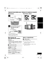
Page 21: ...eleccionar la hora y luego presione OK Spanish Quick Reference Referencia rápida en español 1 2 Cinta adhesiva no suministrado Antena interior FM suministrado Conecte el cable de alimentación AC después de que todas las demás conexiones estén completas Hacia el tomacorriente AC Cable de alimentación AC suministrado Lado de la etiqueta Reproducción básica Reproducir Presione 1 Detención Presione Pa...

Page 22: ...r other business or rental use of the product or service by anyone other than a Factory Service Center or other Authorized Servicer or damage that is attributable to acts of God THERE ARE NO EXPRESS WARRANTIES EXCEPT AS LISTED UNDER LIMITED WARRANTY COVERAGE THE WARRANTOR IS NOT LIABLE FOR INCIDENTAL OR CONSEQUENTIAL DAMAGES RESULTING FROM THE USE OF THIS PRODUCT OR ARISING OUT OF ANY BREACH OF TH...

Page 23: ...trols improper maintenance power line surge lightning damage modification introduction of sand humidity or liquids commercial use such as hotel office restaurant or other business or rental use of the product or service by anyone other than an Authorized Servicer or damage that is attributable to acts of God Dry cell batteries are also excluded from coverage under this warranty THIS EXPRESS LIMITE...

Page 24: ...Newark NJ 07102 5490 http www panasonic com C Panasonic Corporation 2013 Printed in Malaysia Panasonic Canada Inc 5770 Ambler Drive Mississauga Ontario L4W 2T3 www panasonic com RQT9882 4P F1113BM4044 pr SC HC39_PPC RQT9882_mst book 24 ページ 2014年3月26日 水曜日 午後2時12分 ...
Reviews: