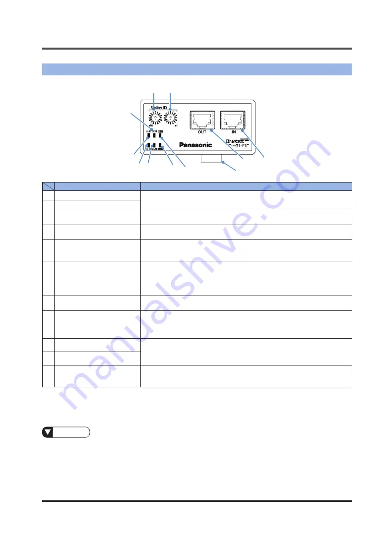
1.5 Name and Function of Each Component
WUME-SCHG1ETC-2
1-7
1.5 Name and Function of Each Component
1
2
3
4
5
11
10
9 8
7
6
Name
Function
1
Station ID (x16)
Rotary switch for setting a station alias. (Note 1)
[Station aliases can be set between 00 and FF]
2
Station ID (x1)
3
IN
RJ45 connector for EtherCAT connection. This connector connects the master
device and the Ethernet cable.
4
OUT
RJ45 connector for EtherCAT connection. This connector connects the slave
device and the Ethernet cable.
5
Male connector for lateral
connection
This connector connects a controller (master unit or slave unit). Electric power
required for the communication unit is supplied from the master unit or slave
unit through this connector.
6
ERR. indicator (Red)
This indicator indicates the state of communication between the communica-
tion unit and the controller connected to it.
OFF: Normal operation state
ON: Communication error occurs between the communication unit and the
controller
7
POWER indicator (Green)
OFF : The power is OFF
ON : The power is ON
8
RUN indicator (Green)
OFF: INIT state
Flashing {single flash (Note 2)}: SAFE-OPERATIONAL state
Flashing {blinking (Note 3)}: PRE-OPERATIONAL state
ON: OPERATIONAL state
9
L/A IN indicator (Green)
OFF : The communication unit is not connected to the Ethernet
Flashing : Link is normal and data is sent or received
ON : Link is normal and data is not sent or received
10
L/A OUT indicator (Green)
11
ECAT ERR indicator (Red)
OFF : Normal operation state
Flashing {Double flash (Note 4)} : Watchdog timeout occurs
Flashing {Blinking (Note 3)} : Configuration error occurs
Notes: 1) For numerical display on the switch, refer to each switch.
2) The indicator repeatedly lights for 0.2 seconds and goes out for 1 second.
3) The indicator repeatedly lights for 0.2 seconds and goes out for 0.2 seconds.
4) The indicator repeatedly lights for 0.2 seconds, goes out for 0.2 secondslights up for 0.2 seconds, and goes,
out for 1 second in this order.
Reference
●
For details on how to set EtherCAT station aliases, refer to
manuals for the EtherCAT master device and configuration tool that you use.
● For details on how to configure EtherCAT operation settings, refer to
Summary of Contents for SC-HG1-ETC
Page 2: ...WUME SCHG1ETC 2 2 MEMO ...
Page 14: ...WUME SCHG1ETC 2 1 8 MEMO ...
Page 20: ...WUME SCHG1ETC 2 2 6 MEMO ...
Page 30: ...WUME SCHG1ETC 2 3 10 MEMO ...
Page 80: ...WUME SCHG1ETC 2 4 50 MEMO ...
Page 90: ...WUME SCLG2CEFP 2 5 10 MEMO ...
Page 91: ...6 1 6 Specification and Dimensions 6 1 Specifications 6 2 6 2 Dimensions 6 3 ...
Page 94: ...WUME SCHG1ETC 2 6 4 MEMO ...
Page 95: ...7 1 7 Warranty 7 1 Important Information about Order and Use of This Product 7 2 ...
Page 98: ...WUME SCHG1ETC 2 7 4 MEMO ...
Page 101: ...9 1 9 Troubleshooting 9 1 Error Codes and Solutions 9 2 9 2 Solutions to Problems 9 4 ...
Page 108: ...10 2 Sample Program WUME SCHG1ETC 2 10 4 10 2 Sample Program 1 2 3 4 5 6 ...
Page 114: ... MEMO ...
Page 115: ... MEMO ...


