


5.2 Example of Operating Procedure after Power ON
WUME-SCHG1ETC-2
5-7
5.2 Example of Operating Procedure after Power ON
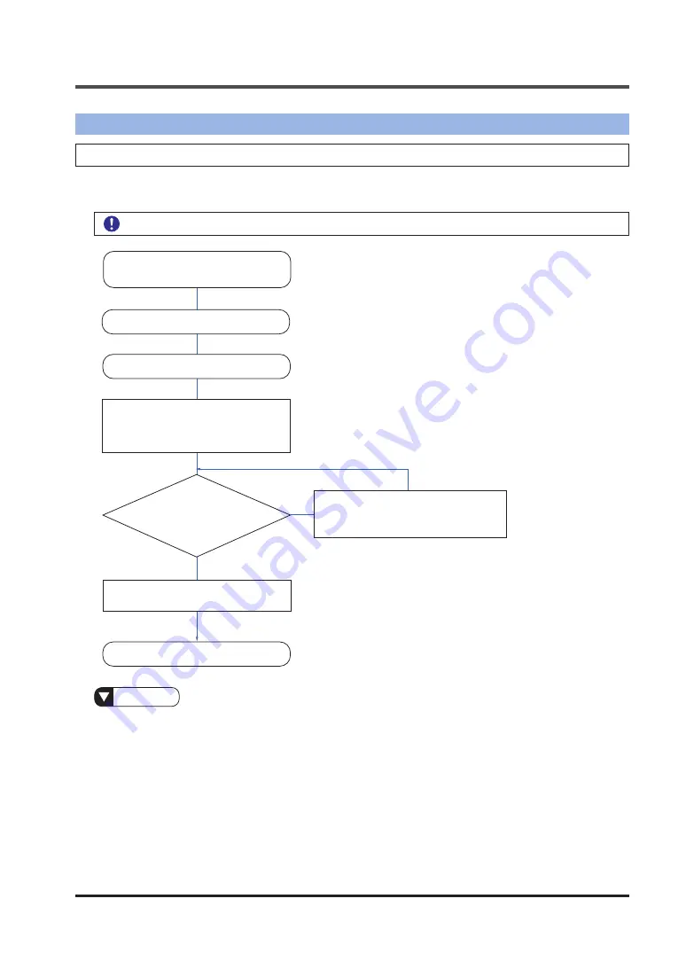
5.2.1 Operation Flow
This section explains the operating procedure that is used after EtherCAT communications are
set up using Control Motion Integrator.
To configure axes or register slaves, complete setup beforehand.
Reference
●
The network connection status can be checked by monitoring the unit memories. Abnormal slave
information is stored in the unit memories (UM 0012E to UM 00139).
●
For details on how to check errors, refer to
“5.5 Checking Error Information”
.
Turn OFF the
FP7
MC unit
and servo amplifier
Turn ON the servo amplifier
Are any error-
related LEDs lit on the display
of the
FP7
MC unit, the servo
amplifier, or this
product?
End of check
Turn ON the
FP7
MC unit
Check whether the LEDs related
to RUN states of the
FP7
MC unit,
servo amplifier, and this product are
lit or blinking
Check whether link establishment
X[+0] is ON
YES
NO
Refer to
the
FP7
Motion Control Unit
User’s Manual
Summary of Contents for SC-HG1-ETC
Page 2: ...WUME SCHG1ETC 2 2 MEMO ...
Page 14: ...WUME SCHG1ETC 2 1 8 MEMO ...
Page 20: ...WUME SCHG1ETC 2 2 6 MEMO ...
Page 30: ...WUME SCHG1ETC 2 3 10 MEMO ...
Page 80: ...WUME SCHG1ETC 2 4 50 MEMO ...
Page 90: ...WUME SCLG2CEFP 2 5 10 MEMO ...
Page 91: ...6 1 6 Specification and Dimensions 6 1 Specifications 6 2 6 2 Dimensions 6 3 ...
Page 94: ...WUME SCHG1ETC 2 6 4 MEMO ...
Page 95: ...7 1 7 Warranty 7 1 Important Information about Order and Use of This Product 7 2 ...
Page 98: ...WUME SCHG1ETC 2 7 4 MEMO ...
Page 101: ...9 1 9 Troubleshooting 9 1 Error Codes and Solutions 9 2 9 2 Solutions to Problems 9 4 ...
Page 108: ...10 2 Sample Program WUME SCHG1ETC 2 10 4 10 2 Sample Program 1 2 3 4 5 6 ...
Page 114: ... MEMO ...
Page 115: ... MEMO ...