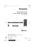
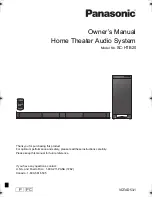
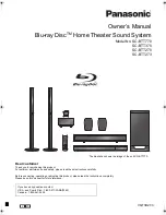
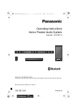
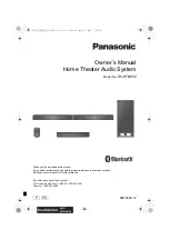
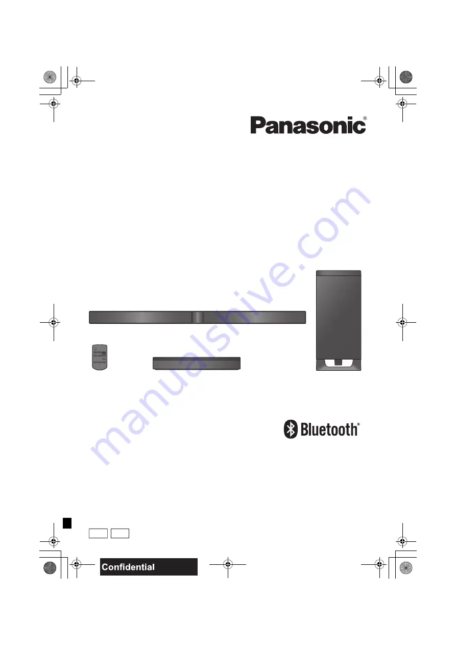
background image

until 

2012/04/30

Owner’s Manual

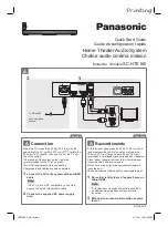
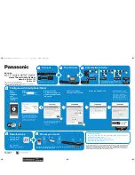
Home Theater Audio System

Model No.

 SC-HTB550

 P

Thank you for purchasing this product.
For optimum performance and safety, please read these instructions carefully.
Please keep this manual for future reference.

If you have any questions, contact:
U.S.A. and Puerto Rico: 1-800-211-PANA (7262)
Canada: 1-800-561-5505

RQT9660-1P

PC

SC-HTB550_RQT9660-1P_mst.book  Page 1  Monday, March 5, 2012  11:03 AM

Summary of Contents for SC-HTB550

Page 1: ...s product For optimum performance and safety please read these instructions carefully Please keep this manual for future reference If you have any questions contact U S A and Puerto Rico 1 800 211 PANA 7262 Canada 1 800 561 5505 RQT9660 1P PC SC HTB550_RQT9660 1P_mst book Page 1 Monday March 5 2012 11 03 AM ...

Page 2: ... electric shock or product damage j Do not expose this unit to rain moisture dripping or splashing j Do not place objects filled with liquids such as vases on this unit j Use only the recommended accessories j Do not remove covers j Do not repair this unit by yourself Refer servicing to qualified service personnel Button type battery Lithium battery Risk of fire explosion and burns Do not disassem...

Page 3: ...RISK OF ELECTRIC SHOCK DO NOT REMOVE SCREWS NO USER SERVICEABLE PARTS INSIDE REFER SERVICING TO QUALIFIED SERVICE PERSONNEL CAUTION RISK OF ELECTRIC SHOCK DO NOT OPEN THE FOLLOWING APPLIES ONLY IN THE U S A FCC Note This equipment has been tested and found to comply with the limits for a Class B digital device pursuant to Part 15 of the FCC Rules These limits are designed to provide reasonable pro...

Page 4: ...le 14 Additional speaker fall prevention measures 17 Step 3 Connections 19 Connection with the TV 19 Connection with other devices 20 Speaker cable connection 21 AC power supply cord connection 21 Active subwoofer wireless connection 22 Bluetooth connection 22 Operations Using this unit 23 3D sound 24 Audio output modes 24 Linked operations with the TV VIERA LinkTM HDAVI ControlTM 25 Advanced oper...

Page 5: ...s shown may differ from your unit Operations in this Owner s Manual are described mainly with the remote control but you can perform the operations on the main unit if the controls are the same System SC HTB550 1 Main unit SU HTB550 1 Active subwoofer SB HWA550 2 Front speakers SB HTB550 Accessories 1 Remote control with a battery N2QAYC000063 2 AC power supply cords K2CB2YY00059 2 Speaker cables ...

Page 6: ...audio source 6 Audio format indicators 1 F Dolby Digital indicator Lights when Dolby Digital is the current audio format G DTS indicator Lights when DTS is the current audio format H PCM indicator Lights when PCM 2ch Multi channel is the current audio format 7 WIRELESS LINK indicator 22 1 AC IN terminal 21 2 Speaker terminals 21 3 TV terminal 19 4 AUX2 terminal 20 5 HDMI OUT terminal ARC compatibl...

Page 7: ...lace a button type battery 1 While pressing the stopper B pull out the battery holder 2 Set the button type battery with its i mark facing upward and then put the battery holder back in place When replacing the battery use CR2025 Lithium battery Keep the button type battery out of reach of children to prevent swallowing Remote control operation range The remote control signal sensor is located on ...

Page 8: ...ll When placing the speakers on a table Place the speakers horizontally Page 10 Place the speakers vertically Place the speakers using the stands Place the speakers using the speaker bases Page 12 Page 14 Page 15 Page 16 Place the speakers using the support legs and speaker feet SC HTB550_RQT9660_mst book Page 8 Tuesday December 20 2011 1 55 PM ...

Page 9: ...ou experience a sudden change in performance Do not attempt to attach these speakers to a wall using methods other than those described in this manual Speaker system When attaching the speakers to a wall The wall or pillar on which the speakers are to be attached should be capable of supporting 33 kg 72 8 lbs per screw Consultation with a qualified installation specialist is recommended when attac...

Page 10: ...terchangeable When attaching the speakers to a wall Place the speakers horizontally 2 Speakers 2 Speaker cables L WHITE R RED 1 Speaker joint 4 Screws A shaped slit Insert the speaker joint fully into the slit B Screw supplied Be sure to insert the screws following the order as indicated in the illustration Keep the screws out of reach of children to prevent swallowing 2 4 1 3 SC HTB550_RQT9660_ms...

Page 11: ...aker The position on the wall where the screw is to be attached as well as the screw should be capable of supporting over 33 kg 72 8 lbs Keep the screws out of reach of children to prevent swallowing 1 Insert the wire fully r White s Blue line 2 Press into the groove A RED Right speaker channel R B WHITE Left speaker channel L C At least 30 mm 1 3 16q D 4 0 mm 5 32q E 7 0 mm to 9 4 mm 9 32q to 3 8...

Page 12: ...aments The two speakers are interchangeable Keep the screws out of reach of children to prevent swallowing DO DO NOT Move the speaker so that the screw is in this position In this position the speaker will likely fall if moved to the left or right Place the speakers vertically 2 Speakers 2 Speaker cables L WHITE R RED 2 Front ornaments 4 Screws Front view Rear view SC HTB550_RQT9660 1P_mst book Pa...

Page 13: ...ker s securely onto the screw s Place the speaker that is connected with the speaker cable with a red connector on the observers right and connect with the speaker cable with a white connector on the observers left 1 Insert the wire fully r White s Blue line 2 Press into the groove A At least 30 mm 1 3 16q B 4 0 mm 5 32q C 7 0 mm to 9 4 mm 9 32q to 3 8q D Wall or pillar E 5 5 mm to 6 5 mm 7 32q to...

Page 14: ...dentify the top and bottom of the speaker Keep the screws out of reach of children to prevent swallowing When placing the speakers on a table Place the speakers using the stands 2 Speakers 2 Speaker cables L WHITE R RED 1 Speaker joint 2 Stands 6 Screws A Screw supplied B Screw hole Align the holes with the projecting parts on the speaker Do not use the lower holes for the alignment If these holes...

Page 15: ...dentify the top and bottom of the speaker Keep the screws and the speaker feet out of reach of children to prevent swallowing Place the speakers using the support legs and speaker feet 2 Speakers 2 Speaker cables L WHITE R RED 1 Speaker joint 6 Screws 2 Support legs 2 Speaker feet A Screw supplied B Screw hole C Speaker foot supplied Attach the speaker foot directly below the wall mounting hole as...

Page 16: ...ble is twisted it might not fit through the opening Straighten the speaker cable before inserting Attach the speaker to the base The two speakers are interchangeable Keep the screws out of reach of children to prevent swallowing Place the speakers using the speaker bases 2 Speakers 2 Speaker cables L WHITE R RED 2 Bases 2 Front ornaments 6 Screws A Threading hole B Screw hole Position the cable be...

Page 17: ... not have strong enough support is recommended 11 13 Improper attachment may result in damage to the wall and speakers and personal injury Use a cord that is capable of supporting over 10 kg 22 05 lbs with a diameter of about 1 5 mm 1 16q Keep the screws out of reach of children to prevent swallowing Make sure that the slack of the cord is minimal Additional speaker fall prevention measures When a...

Page 18: ...ent of the speakers the screwing position of the screw eye may differ C Wall D Approx 150 mm 5 29 32q If the cord cannot be threaded through the holes try bending the cord in 2 locations about 10 mm 13 32q apart from the tip at an angle of 45o as illustrated above SC HTB550_RQT9660 1P_mst book Page 18 Monday March 5 2012 11 03 AM ...

Page 19: ...optical digital audio cable that is usually required in order to listen to sound from a TV is no longer required and TV pictures and sound can be enjoyed with a single HDMI cable Make the connection Connection with the TV Connection differs depending on the label printed next to the HDMI terminal Labeled HDMI ARC Connection A Not Labeled HDMI ARC Connection B A Labeled HDMI ARC A HDMI cable B Not ...

Page 20: ...FULL HD 3D TV and Blu ray Disc playerTM The main unit can pass the 3D video signal from a 3D compatible Blu ray Disc playerTM to a FULL HD 3D TV Connection with other devices When the device has an HDMI terminal A HDMI cable When the device has an optical digital audio output terminal B Refer to the operating instructions of the respective devices for the optimal connection C Optical digital audio...

Page 21: ... WHITE Left speaker channel L AC power supply cord connection C AC power supply cord D To a household AC outlet Install this unit so that the power cord can be unplugged from the socket outlet immediately if any problem occurs Saving energy The main unit is designed to conserve its power consumption and save energy The main unit will automatically switch to standby mode when no signal is input and...

Page 22: ...vice is connected the indicator stops flashing and lights up Refer to the operating instructions of the Bluetooth device for further instruction on how to connect a Bluetooth device If prompted for the passkey on the Bluetooth device enter 0000 Press j PAIRING Press and hold the j PAIRING until the indicator flashes quickly Repeat step 2 of Pairing a device You can register up to 6 devices with th...

Page 23: ...s displayed Press i DIALOG LEVEL j to adjust the level To adjust the subwoofer level 1 Press i SUBWOOFER j to display the current level 2 While the level is displayed Press i SUBWOOFER j to adjust the level The level indication pattern is the same as dialog effect level To mute the sound Press MUTE While muting the audio format indicators blink simultaneously To cancel press the button again or ad...

Page 24: ... Speaker and the 3D surround effect will be temporarily canceled if the audio signal s sampling frequency is greater than 48 kHz 3D sound 3D sound Dolby Virtual Speaker With this effect you can enjoy a surround sound effect similar to 5 1ch 3D surround effect Adding to the Dolby Virtual Speaker effect Panasonic has applied its own sound field controlling technology to expand the sound field forwar...

Page 25: ...e settings may vary depending on the TV Refer to the operating instructions for the TV for details Speaker control You can select whether audio output is from this system or the TV speakers by using the TV menu settings Home theater This system is active When this system is in standby mode changing the TV speakers to this system in the VIERA Link menu will automatically turn this system on and sel...

Page 26: ...ce indicator will blink slowly Press LINK MODE to display the current mode The indicator for the current setting blinks for 10 sec While the mode is displayed press LINK MODE to select the mode The setting changes each time LINK MODE is pressed The setting is maintained until it is changed again Depending on your preference It is possible to use only the Dolby Virtual Speaker effect by turning off...

Page 27: ... level is still adjustable To turn off VIERA Link HDAVI Control When HDAVI Control compatible equipment does not work well with this system for example it is possible to turn off this function as follows When VIERA Link is turned off the ARC function is not available Be sure to connect the optical digital audio cable 19 1 Press and hold MUTE on the remote control and followed by s VOL on the main ...

Page 28: ... connected devices Have you turned the VIERA Link settings off 27 When the HDMI connections are changed after a power failure or after the AC power supply cord has been removed VIERA Link operations may not function properly j Turn on all the devices that are connected to the TV with an HDMI cable and then turn the TV on j Turn off the VIERA Link settings of the TV and turn it on again For details...

Page 29: ...on to make the dialog stand out when the volume is low 27 There is no audio The power of the main unit turns off automatically When the main unit detects a problem a safety measure is activated and the main unit automatically switches to standby mode There is a problem with the amplifier Is the volume extremely high If so lower the volume Is this system placed in an extremely hot place If so move ...

Page 30: ...for 10 sec When the audio output mode is Auto mode 24 When the dialog effect level or the subwoofer level is 2 23 The indicator blinks for 10 sec When the audio output mode is Auto mode 24 The indicators blink for 10 sec When the dialog effect level or the subwoofer level is 3 23 The indicator blinks for 10 sec When the audio output mode is 2ch mode 24 When 3D surround effect and clear mode dialog...

Page 31: ...an equipment or in an environment that is sensitive to radio frequency interference example airports hospitals laboratories etc Unit care Clean the system with a soft dry cloth When dirt is heavy wring a cloth moistened in water tightly to wipe the dirt and then wipe it with a dry cloth When cleaning the system use a fine cloth Do not use tissues or other materials towels etc that can fall apart S...

Page 32: ...l DTS SPEAKER SECTION Front speakers 2 way 2 speaker system Bass reflex type Speaker unit s Impedance 6 Woofer 6 5 cm 2 1 2q cone typek1 Tweeter 2 5 cm 1q semi dome typek1 Frequency range 100 Hz to 30 kHz 16 dB 150 Hz to 25 kHz 10 dB Active subwoofer 1 way 1 speaker system Bass reflex type Woofer 16 cm 6 1 2q cone typek1 Frequency range 30 Hz to 180 Hz 16 dB 35 Hz to 160 Hz 10 dB GENERAL Power con...

Page 33: ...tal placement for wall mount Dimensions WkHkD 956 mmk75 mmk35 mm 37 5 8qk2 15 16qk1 3 8q Mass Weight 1 54 kg 3 5 lbs Vertical placement using the speaker bases Dimensions WkHkD 148 mmk528 mmk145 mm 5 13 16qk20 25 32qk5 23 32q Mass Weight 0 88 kg 1 98 lbs Vertical placement for wall mount Dimensions WkHkD 75 mmk478 mmk35 mm 2 15 16qk18 13 16qk1 3 8q Mass Weight 0 77 kg 1 76 lbs Bluetooth SECTION Bl...

Page 34: ...or other Authorized Servicer or damage that is attributable to acts of God THERE ARE NO EXPRESS WARRANTIES EXCEPT AS LISTED UNDER LIMITED WARRANTY COVERAGE THE WARRANTOR IS NOT LIABLE FOR INCIDENTAL OR CONSEQUENTIAL DAMAGES RESULTING FROM THE USE OF THIS PRODUCT OR ARISING OUT OF ANY BREACH OF THIS WARRANTY As examples this excludes damages for lost time travel to and from the servicer loss of or ...

Page 35: ...ent of consumer controls improper maintenance power line surge lightning damage modification introduction of sand humidity or liquids commercial use such as hotel office restaurant or other business or rental use of the product or service by anyone other than an Authorized Servicer or damage that is attributable to acts of God Dry cell batteries are also excluded from coverage under this warranty ...

Page 36: ...2 If you see this symbol Information on Disposal in other Countries outside the European Union This symbol is only valid in the European Union If you wish to discard this product please contact your local authorities or dealer and ask for the correct method of disposal As an ENERGY STAR Partner Panasonic has determined that this product meets the ENERGY STAR guidelines for energy efficiency For Ca...

Reviews: