If several errors are detected, press the
button to display each.
14.3.2. Re-Display
•
•
•
•
Press the power button to turn off the power, and then turn on the power.
•
•
•
•
The details of self diagnosis are stored in the unit memory.
To retrieve them, follow the procedure described the above, “Activating Self-Diagnosis Function and Displaying Method”.
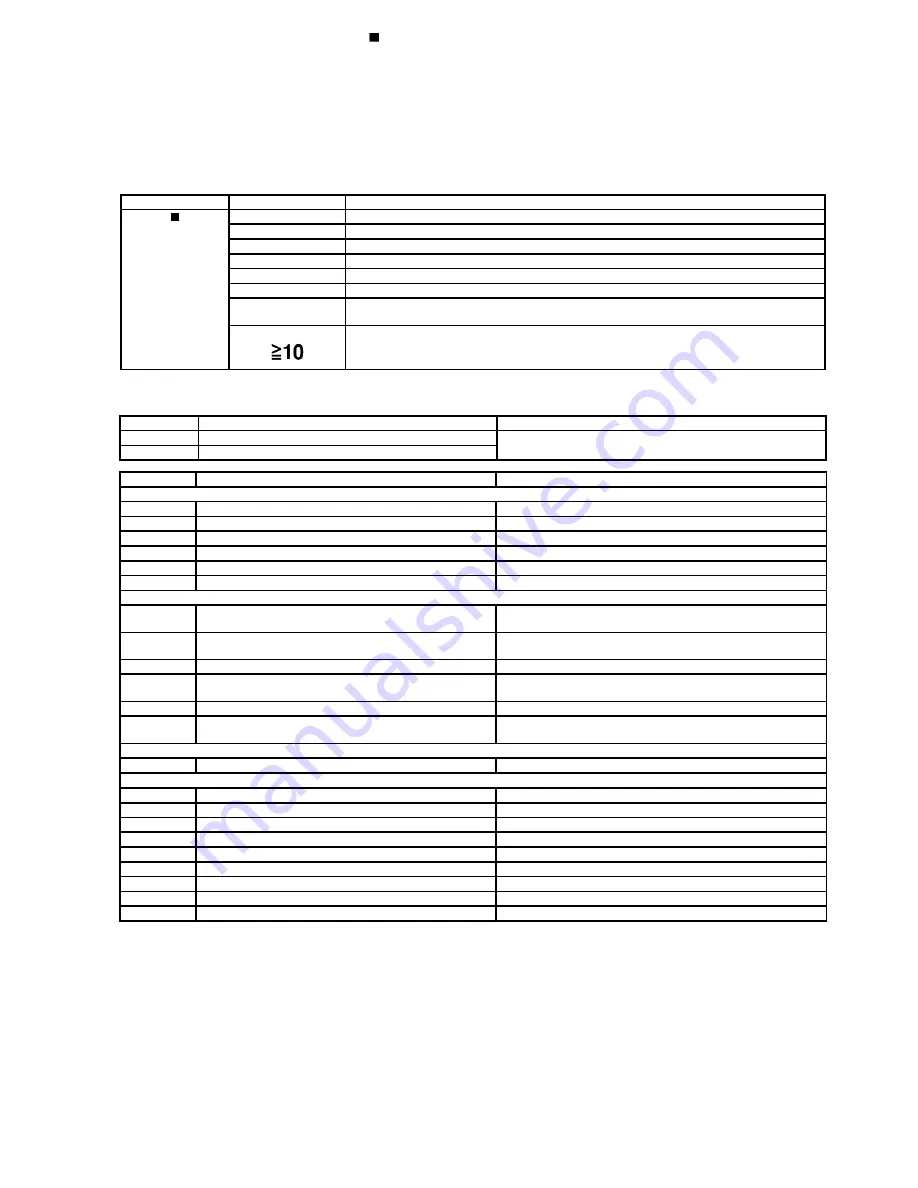
14.4. Service Mode Table 1
Following modes are available with combinations of the pressed buttons on the player and on the remote controller unit.
Player
Remote Controller Unit
Usage
button
0
Error code display (Refer to the Item 14.5. DVD/CD Self-Diagnosis Error Code Description)
5
Tilt adjustment (Jitter)
6
Region number and broadcasting system check
8
Bulit-in program version check (Micro-P)
DISPLAY
DVD laser drive current check
3
CD laser drive current check
PAUSE
Writing of laser drive current value after replacement of optical pickup
(Do use this function only when optical pickup is replaced.)
Initialization of the player (factory setting is restored.)
Used after replacement of micro-computer and its peripherals and printed circuit board.
14.5. DVD/CD Self-Diagnosis Error Code Description
Error Code
State, Conditon
Cause, Troubleshooting
H15
The disc tray cannot be opened: it closes spontaneously.
Disc tray open/close detection switch (S1001) failure.
(Check and replace)
H16
The disc tray cannot be closed: it opens spontaneously.
Error Code
Meaning
Details
U. H. Error
U11
Focus servo failure
H01
Tray loading failure
H02
Spindle servo failure
(Spindle servo, DSC, SP motor, CLV servo failure)
H03
Traverse motor failure
H04
Tracking servo error
H05
Seek timeout failure
DSC system
F500
DSC failure
DSC stops due to servo failure.
(Startup, focus failure, etc.)
F501
DSC not Ready failure
Communication failure between DSC and system computer
(No communication because DSC does not move)
F502
DSC Time out failure
See F500.
F503
DSC communication failure
Communication failure (Result failure occurs after communication
command is transmitted.)
F505
DSC Attention Error
See F500.
F506
Invalid media
Disc is placed upside down; TOC is unreadable or invalid disc is
inserted.
Disc Code
F103
Ilegal highlight position
Disc standard is possibly illegal when highlight is displayed.
IIC Error
F4FF
Forced initialization failure (Time out)
F880
Unsuitable task number
When a message arrives from not existing task
F890
A message is sent during AV task transmission
During transmission of a message to AV task
F891
Unable to transmit a message to AV task
When transmission of a message to AV task starts
F893
DVD Module problem
Check for firmware version
F894
EEPROM failure
F895
Firmware compatibility problem
Check for firm version for Main & DVD Module P.C.B.
F897
Initialization is not done properly
Follow proper steps for initialization & reset
F8A0
Unsuitable message command
When transmission of a message to AV task starts
14.6. Mode Table 2
Following modes are available with combinations of the pressed buttons on the player and on the remote controller unit.
19
Summary of Contents for SC-TM900DVD
Page 9: ...10 Operation Procedures 9 ...
Page 10: ...10 ...
Page 11: ...11 Disc information 11 ...
Page 12: ...12 ...
Page 15: ...15 ...
Page 35: ...Step 2 Remove DVD traverse deck by rotating to the arrow direction 35 ...
Page 39: ...39 ...
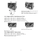
Page 40: ...16 17 3 Replacement for the traverse deck Follow the Step 1 Step 10 of item 16 17 2 40 ...
Page 42: ...42 ...
Page 43: ...43 ...
Page 45: ...45 ...
Page 46: ...46 ...
Page 47: ...47 ...
Page 48: ...48 ...
Page 49: ...49 ...
Page 50: ...50 ...
Page 51: ...51 ...
Page 52: ...52 ...
Page 53: ...53 ...
Page 54: ...54 ...
Page 55: ...55 ...
Page 65: ...18 3 1 Cassette Deck Section 18 3 2 Adjustment Point 18 3 Alignment Points 65 ...
Page 77: ...20 Voltage Measurement This section is not available at time of issue 77 ...
Page 107: ...35 6 6 7 7 7 7 7 7 6 U 2 2 2 0 2 1 2 2 1 2 2 1 2 1 2 2 2 4 6 35 ...
Page 109: ...0 7 7 7 2 2 2 3 4 6 EW ODEL GT IC OTE ATERIAL 3IZE MODIFIED 0 4 25 ...
Page 110: ...2 0 7 2 0 5NIT MM 0ARTS NO AME PPROVED HECKED 3 ...
Page 111: ......
Page 112: ......
Page 113: ......
Page 114: ......
Page 115: ......
Page 116: ...116 ...
Page 117: ...117 ...
Page 139: ...26 1 Deck Mechanism RAA3413 S 26 1 1 Deck Mechanism Parts Location 139 ...
Page 140: ...140 ...
Page 142: ...26 2 DVD Loading Mechanism 26 2 1 DVD Loading Mechanism Parts Location 142 ...
Page 143: ...143 ...
Page 145: ...26 3 Cabinet 26 3 1 Cabinet Parts Location 145 ...
Page 146: ...146 ...
Page 147: ...147 ...
Page 188: ...3 Connection of the Wiring Diagram 4 Cabinet Parts Location 5 service m speaker 11 ...
Page 192: ...3 Connection of the Wiring Diagram 9 service m speaker ...
Page 193: ...4 Cabinet Parts Location 3 10 service m speaker ...
Page 198: ...3 Connection of the Wiring Diagram 4 Cabinet Parts Location 15 service m speaker ...
Page 203: ...3 Connection of the Wiring Diagram 4 Cabinet Parts Location 20 service m speaker ...


