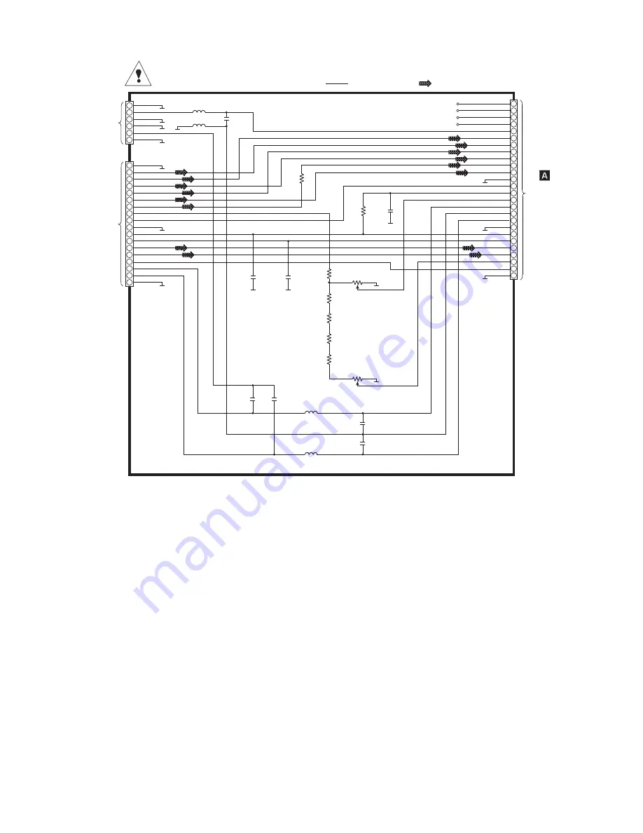
21.1. Optical Pickup Unit Circuit
2
4
6
5
3
1
15
14
13
12
11
10
2
4
6
8
9
7
5
3
1
17
18
16
16
17
18
19
20
21
25
23
22
24
26
1
2
3
4
5
6
14
12
10
8
7
9
11
13
15
TO ACT
TO
DVD MODULE
CIRCUIT
(FP8501) ON
SCHEMATIC
DIAGRAM - 2
TO
HFM
PCB
TO
LDU
PCB
L4
J0JBC0000105
L1
J0JBC0000105
L2
J0JCC0000307
C5
22P
C6
22P
C1
0.1
C3
0.1
C2
0.1
R1
0
R4
0
R2
0
C8
0.1
R3
0
R5
0
R6
0
R7
6.8K
C7
0.1
VR2
6.8K
VR1
6.8K
C4
0.22
L3
J0JBC0000105
T+
F+
F-
T-
HFM
TA
TB
TD
TC
FE2
FE1
GND (IM)
RF
VREF2(RF-)
PIN (DVD)
LD (CD)
LD GND
LD (DVD)
GND (OEIC)
VREF1
VCC
SUB2
SUB1
PIN(CD)
SW
GND (IM)
GND
VCC
GND
GND
OUT
GND
GND
TB
TA
TC
TD
FE1
FE2
IM
RF
GND
VREF
VCC
SUB2
SUB1
SW
LD (CD)
LD (DVD)
LDGND
SCHEMATIC DIAGRAM - 1
OPTICAL PICKUP UNIT CIRCUIT
: +B SIGNAL LINE
: CD-DA SIGNAL LINE
79
Summary of Contents for SC-TM900DVD
Page 9: ...10 Operation Procedures 9 ...
Page 10: ...10 ...
Page 11: ...11 Disc information 11 ...
Page 12: ...12 ...
Page 15: ...15 ...
Page 35: ...Step 2 Remove DVD traverse deck by rotating to the arrow direction 35 ...
Page 39: ...39 ...
Page 40: ...16 17 3 Replacement for the traverse deck Follow the Step 1 Step 10 of item 16 17 2 40 ...
Page 42: ...42 ...
Page 43: ...43 ...
Page 45: ...45 ...
Page 46: ...46 ...
Page 47: ...47 ...
Page 48: ...48 ...
Page 49: ...49 ...
Page 50: ...50 ...
Page 51: ...51 ...
Page 52: ...52 ...
Page 53: ...53 ...
Page 54: ...54 ...
Page 55: ...55 ...
Page 65: ...18 3 1 Cassette Deck Section 18 3 2 Adjustment Point 18 3 Alignment Points 65 ...
Page 77: ...20 Voltage Measurement This section is not available at time of issue 77 ...
Page 107: ...35 6 6 7 7 7 7 7 7 6 U 2 2 2 0 2 1 2 2 1 2 2 1 2 1 2 2 2 4 6 35 ...
Page 109: ...0 7 7 7 2 2 2 3 4 6 EW ODEL GT IC OTE ATERIAL 3IZE MODIFIED 0 4 25 ...
Page 110: ...2 0 7 2 0 5NIT MM 0ARTS NO AME PPROVED HECKED 3 ...
Page 111: ......
Page 112: ......
Page 113: ......
Page 114: ......
Page 115: ......
Page 116: ...116 ...
Page 117: ...117 ...
Page 139: ...26 1 Deck Mechanism RAA3413 S 26 1 1 Deck Mechanism Parts Location 139 ...
Page 140: ...140 ...
Page 142: ...26 2 DVD Loading Mechanism 26 2 1 DVD Loading Mechanism Parts Location 142 ...
Page 143: ...143 ...
Page 145: ...26 3 Cabinet 26 3 1 Cabinet Parts Location 145 ...
Page 146: ...146 ...
Page 147: ...147 ...
Page 188: ...3 Connection of the Wiring Diagram 4 Cabinet Parts Location 5 service m speaker 11 ...
Page 192: ...3 Connection of the Wiring Diagram 9 service m speaker ...
Page 193: ...4 Cabinet Parts Location 3 10 service m speaker ...
Page 198: ...3 Connection of the Wiring Diagram 4 Cabinet Parts Location 15 service m speaker ...
Page 203: ...3 Connection of the Wiring Diagram 4 Cabinet Parts Location 20 service m speaker ...


