142
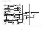
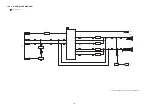
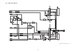
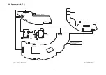
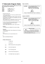
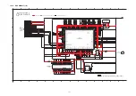
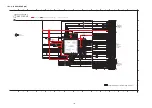
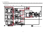
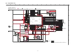
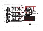
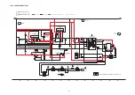
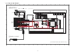
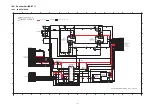
17 Schematic Diagram Notes
(All schematic diagrams may be modified at any time with
the development of new technology)
Notes:
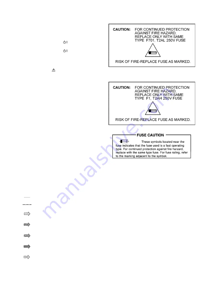
• Important safety notice:
Components identified by
mark have special characteris-
tics important for safety.
Furthermore, special parts which have purposes of fire-retar-
dant (resistors), high quality sound (capacitors), low-noise
(resistors), etc are used.
When replacing any of components, be sure to use only
manufacturer’s specified parts shown in the parts list.
• In case of AC rated voltage Capacitors, the part no. and val-
ues will be indicated in the Schematic Diagram.
AC rated voltage capacitors:
C5501, C5502, C5509, C5700, C5701, C5703, C5704
•
Resistor
Unit of resistance is OHM [
Ω
] (K=1,000, M=1,000,000).
•
Capacitor
Unit of capacitance is
μ
F, unless otherwise noted. F=Farads,
pF=pico-Farad.
•
Coil
Unit of inductance is H, unless otherwise noted.
•
*
REF IS FOR INDICATION ONLY.
•
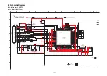
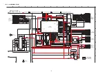
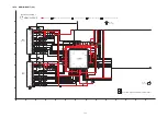
Voltage and Signal lines:
Main Unit (SU-ZT1)
Speaker Unit (SB-ZT1)
S4601:
POWER switch. (
).
S4602:
SELECTOR switch.
S6001:
POWER switch. (
).
S6051:
ID SET switch.
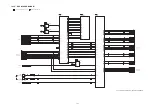
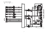
: +B signal line
: -B signal line
: BD/DVD Audio & Video Input signal line
: Audio Output signal line
: Video Output signal line
: Audio & Video Output signal line
: AUX/Optical Audio Input signal line
Summary of Contents for SC-ZT1GN
Page 4: ...4 1 2 Caution for AC Mains Lead ...
Page 11: ...11 5 Location of Controls and Components 5 1 Main Unit SU ZT1 ...
Page 12: ...12 5 2 Speaker Unit SB ZT1 5 3 Remote Control ...
Page 13: ...13 6 Installation ...
Page 14: ...14 6 1 Basic Connections 6 1 1 Connecting equipment with HDMI terminal TV DVD recorder etc ...
Page 15: ...15 6 1 2 Connecting equipment without HDMI termial DVD player VCR etc ...
Page 16: ...16 6 1 3 Other connections ...
Page 17: ...17 6 2 AC mains lead connection ...
Page 18: ...18 7 Speaker setting SB ZT1 7 1 Setting the speakers ...
Page 19: ...19 ...
Page 27: ...27 9 2 2 Speaker Unit SB ZT1 ...
Page 28: ...28 9 2 3 Speaker Unit SB ZT1 Wireless Link ...
Page 29: ...29 ...
Page 31: ...31 ...
Page 32: ...32 10 2 Main Parts Location Diagram 10 2 1 Main Unit SU ZT1 ...
Page 33: ...33 10 2 2 Speaker Unit SB ZT1 ...
Page 35: ...35 10 3 2 Speaker Unit SB ZT1 ...
Page 48: ...48 Step 4 Remove the Weight ...
Page 49: ...49 Step 5 Remove 10 screws ...
Page 53: ...53 Step 11 Remove 2 screws Step 12 Lift up to remove Arm Cover A ...
Page 55: ...55 Step 14 Tilt the Woofer Block in order as arrows shown to detach it from the Tweeter Block ...
Page 66: ...66 Step 3 Remove the heatsink with the IC5701 ...
Page 67: ...67 Step 4 Remove 1 screw Step 5 Remove IC5701 from the heatsink ...
Page 69: ...69 Step 4 Place the heatsink with the IC5701 onto the SMPS P C B ...
Page 81: ...81 Step 4 Remove 3 screws Step 5 Remove the Power Button ...
Page 86: ...86 Step 3 Remove 4 screws Step 4 Lift up to remove Woofer Speaker SP1 ...
Page 110: ...110 Step 11 Remove 3 screws ...
Page 111: ...111 Step 12 Remove the Light Panel Step 13 Remove the Power Button ...
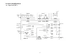
Page 129: ...129 14 Overall Simplified Block 14 1 Signal Flow SU ZT1 ...

