6
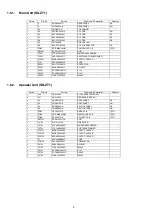
1.6.1.
Main Unit (SU-ZT1)
1.6.2.
Speaker Unit (SB-ZT1)
Safety
Ref. No.
Part No.
Part Name & Description
Remarks
11
RGR0393A-D
REAR PANEL
GS
11
RGR0393A-E
REAR PANEL
GN
30
RKM0613-K
TOP CABINET
A2
K2CJ2DA00010
AC CORD
GN
A2
K2CP2CA00001
AC CORD
GS
A2
K2CQ2CA00007
AC CORD
GS
A2
K2CZ3YY00005
AC CORD
GS
A3
RQT9462-E
O/I BOOK (En)
A9
K2DAYYY00002
AC PLUG ADAPTER
GS
PCB1
RD-DWKX006JM
TX MODULE P.C.B
(RTL)
DZ5501
ERZV10V511CS
ZNR
T5501
ETS25AD1V6AG
MAIN TRANSFORMER
T5551
G4D1A0000117
SWITCHING TRANSFORMER
PC5501
B3PBA0000402
PHOTO COUPLER
F701
K5D202BK0005
FUSE
IP5501
K5H7512A0010
PROTECTOR
P5501
K2AA2B000011
AC INLET
C5501
ECQU2A104MLC
0.1uF
C5502
ECQU2A104MLC
0.1uF
C5509
F1BAF1020020
1000pF
Safety
Ref. No.
Part No.
Part Name & Description
Remarks
100
REX1346-1
BLACK WIRE (SMPS-AC)
101
REX1356-1
RED WIRE (SMPS-AC)
113
RGN2979C-K
SPEC SHEET
GS
113
RGN2979D-K
SPEC SHEET
GN
114
RGN2980C-K
CAUTION LABEL
GS
114
RGN2980D-K
CAUTION LABEL
GN
PCB1
REP4527D-P
SMPS P.C.B
(RTL)
PCB2
RD-DWKX009JM
RX MODULE P.C.B
(RTL)
PCB6
REP4527D-P
AC INLET P.C.B
(RTL)
DZ5701
ERZV10V511CS
ZNR
L5702
ELF19H010A
LINE FILTER
T5701
ETS28BH166AC
MAIN TRANSFORMER
T5751
ETS19AB2C6AG
SUB TRANSFORMER
PC5701
B3PBA0000402
PHOTO COUPLER
PC5720
B3PBA0000402
PHOTO COUPLER
PC5799
B3QAZ0000062
PHOTO COUPLER
F1
K5D202BNA005
FUSE
TH5702
D4CAA5R10001
THERMISTOR
P5701
K2AA2B000011
AC INLET
C5700
F1BAF2220023
2200pF
C5701
ECQU2A104MLC
0.1uF
C5703
ECQU2A224MLC
0.22uF
C5704
F1BAF1020020
1000pF
Summary of Contents for SC-ZT1GN
Page 4: ...4 1 2 Caution for AC Mains Lead ...
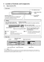
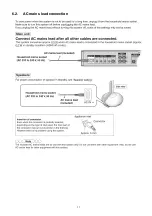
Page 11: ...11 5 Location of Controls and Components 5 1 Main Unit SU ZT1 ...
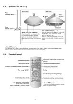
Page 12: ...12 5 2 Speaker Unit SB ZT1 5 3 Remote Control ...
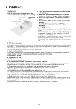
Page 13: ...13 6 Installation ...
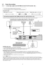
Page 14: ...14 6 1 Basic Connections 6 1 1 Connecting equipment with HDMI terminal TV DVD recorder etc ...
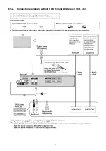
Page 15: ...15 6 1 2 Connecting equipment without HDMI termial DVD player VCR etc ...
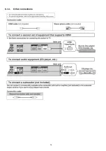
Page 16: ...16 6 1 3 Other connections ...
Page 17: ...17 6 2 AC mains lead connection ...
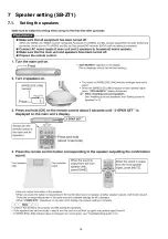
Page 18: ...18 7 Speaker setting SB ZT1 7 1 Setting the speakers ...
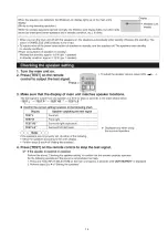
Page 19: ...19 ...
Page 27: ...27 9 2 2 Speaker Unit SB ZT1 ...
Page 28: ...28 9 2 3 Speaker Unit SB ZT1 Wireless Link ...
Page 29: ...29 ...
Page 31: ...31 ...
Page 32: ...32 10 2 Main Parts Location Diagram 10 2 1 Main Unit SU ZT1 ...
Page 33: ...33 10 2 2 Speaker Unit SB ZT1 ...
Page 35: ...35 10 3 2 Speaker Unit SB ZT1 ...
Page 48: ...48 Step 4 Remove the Weight ...
Page 49: ...49 Step 5 Remove 10 screws ...
Page 53: ...53 Step 11 Remove 2 screws Step 12 Lift up to remove Arm Cover A ...
Page 55: ...55 Step 14 Tilt the Woofer Block in order as arrows shown to detach it from the Tweeter Block ...
Page 66: ...66 Step 3 Remove the heatsink with the IC5701 ...
Page 67: ...67 Step 4 Remove 1 screw Step 5 Remove IC5701 from the heatsink ...
Page 69: ...69 Step 4 Place the heatsink with the IC5701 onto the SMPS P C B ...
Page 81: ...81 Step 4 Remove 3 screws Step 5 Remove the Power Button ...
Page 86: ...86 Step 3 Remove 4 screws Step 4 Lift up to remove Woofer Speaker SP1 ...
Page 110: ...110 Step 11 Remove 3 screws ...
Page 111: ...111 Step 12 Remove the Light Panel Step 13 Remove the Power Button ...
Page 129: ...129 14 Overall Simplified Block 14 1 Signal Flow SU ZT1 ...

