6
RQT7969
≥
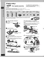
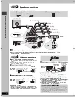
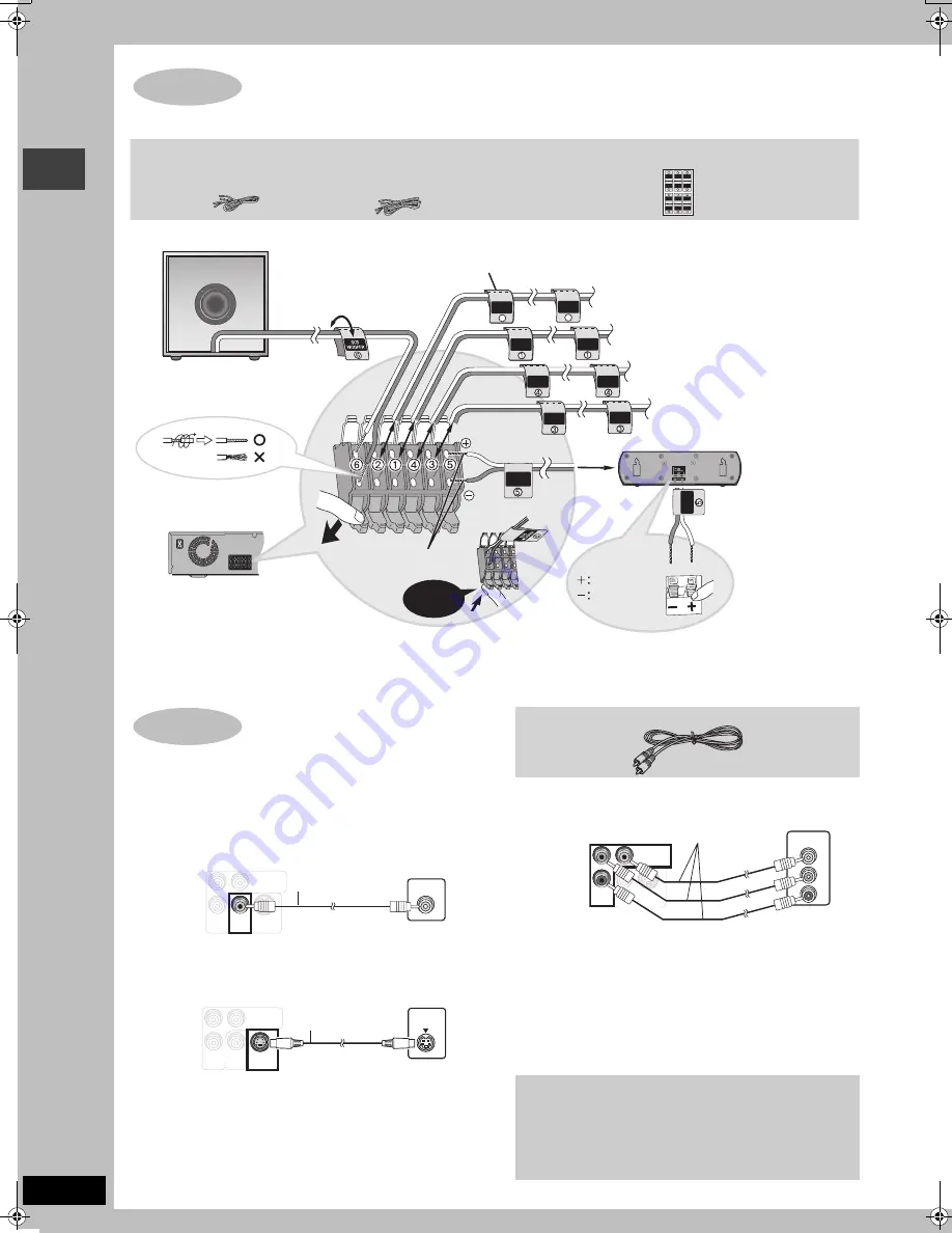
Attach the speaker-cable stickers to make connection easier.
≥
Do not connect through the video cassette recorder.
Due to copy guard protection, the picture may not be displayed
properly.
≥
Turn the television off before connecting, and refer to the
television’s operating instructions.
∫
Television with a VIDEO IN terminal
∫
Television with an S-VIDEO IN terminal
∫
Television with COMPONENT VIDEO IN terminals
COMPONENT VIDEO OUT terminals
These terminals can be used for either interlace or progressive
output and provide a purer picture than the S-VIDEO OUT
terminal. Connection using these terminals outputs the color
difference signals (P
B
/P
R
) and luminance signal (Y) separately in
order to achieve high fidelity in reproducing colors.
≥
The description of the component video input terminals depends
on the television or monitor (e.g. Y/P
B
/P
R
, Y/B-Y/R-Y, Y/C
B
/C
R
).
Connect to terminals of the same color.
≥
After making this connection, select “Darker” from the “Black
Level Control” in the “Video” tab (
➜
page 21).
STEP
3
Speaker connections
4
4
2
2
6
6
5
3
5
3
1
1
SURROUND
Rch
Rch
SURROUND
Rch
Rch
FRONT
WOOFER
SUB
Lch
Lch
Lch
CENTER
Lch
SURROUND
SURROUND
FRONT
SUB
WOOFER
FRONT
FRONT
CENTER
SURROUND
Rch
Rch
FRONT
CENTER
Lch
SURROUND
Lch
FRONT
CENTER
2
2
Rch
FRONT
Lch
FRONT
SURROUND
Rch
Lch
SURROUND
2 Sheets of speaker-cable stickers
3 Speaker cables
≥
1
k
short cable: For center speaker
≥
2
k
long cables: For surround speakers
Speaker-cable sticker
2
FRONT (R)
1
FRONT (L)
4
SURROUND (R)
3
SURROUND (L)
5
CENTER
6
SUBWOOFER
White
Blue
Insert the wire fully.
Click!
[Note]
≥
Never short-circuit positive (
i
) and negative (
j
) speaker wires.
≥
Be sure to connect only positive (white) wires to positive (
i
) terminals and negative (blue) wires to negative (
j
) terminals.
Incorrect connection can damage the speakers.
Main unit
STEP
4
Video connections
S-
V
IDEO
OUT
V
IDEO
V
IDEO
OUT
OUT
COMPO
N
E
N
T
COMPO
N
E
N
T
V
IDEO OUT
V
IDEO OUT
(4
8
0p/4
8
0i)
(4
8
0p/4
8
0i)
P
R
P
B
Y
V
IDEO I
N
Back of the
main unit
Video cable
(included)
Television
(not included)
S-
V
IDEO
S-
V
IDEO
OUT
OUT
V
IDEO
V
IDEO
OUT
OUT
COMPO
N
E
N
T
V
IDEO OUT
(4
8
0p/4
8
0i)
P
R
P
B
Y
S-
V
IDEO
I
N
Television
(not included)
S-video cable
(not included)
Back of the
main unit
S-VIDEO OUT terminal
The S-VIDEO OUT terminal achieves a more vivid picture than
the VIDEO OUT terminal by separating the chrominance (C) and
luminance (Y) signals. (Actual results depend on the television.)
To enjoy progressive video
≥
Connect to the component video input terminals on a 480p
compatible television. (Video will not be displayed correctly if
connected to an incompatible television.)
≥
All Panasonic televisions that have 480p input connectors are
compatible. Consult the manufacturer if you have another
brand of television.
Video cable
S-
V
IDEO
OUT
V
IDEO
OUT
COMPO
N
E
N
T
COMPO
N
E
N
T
V
IDEO OUT
V
IDEO OUT
(4
8
0p/4
8
0i)
(4
8
0p/4
8
0i)
P
R
P
B
Y
COMPO
N
E
N
T
V
IDEO I
N
P
R
P
B
Y
Television
(not included)
Video cables
(not included)
Back of the
main unit
Sp
ea
ker
co
n
n
ect
io
n
s
/V
id
eo
co
n
n
ect
io
n
s
HT680.book Page 6 Tuesday, December 14, 2004 8:55 AM

