R
Q
T
8582
6
Simple
Se
tu
p
∫
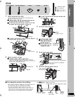
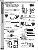
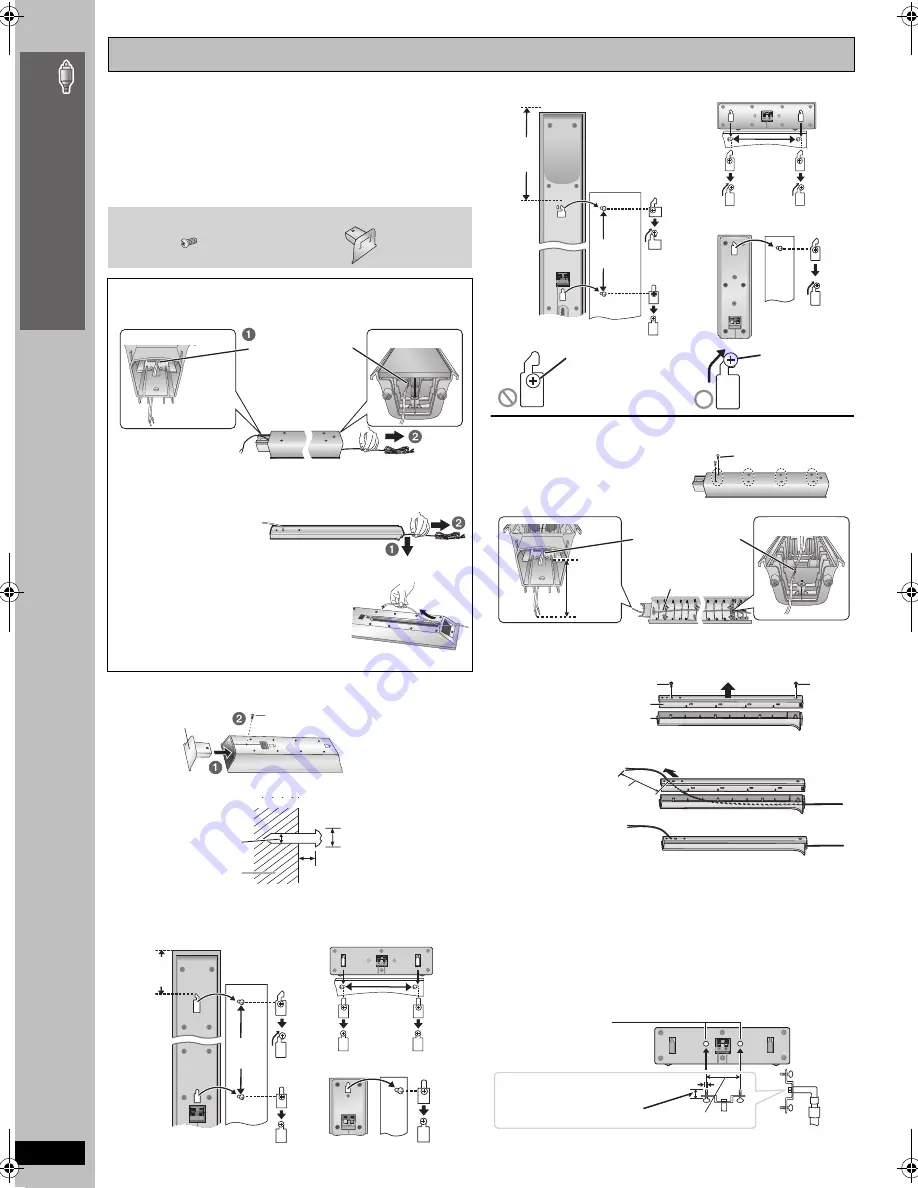
Attaching to a wall
You can attach all of the speakers (except subwoofer) to a wall.
≥
The wall or pillar on which the speakers are to be attached should be
capable of supporting over 10 k
g
(22 lbs) [
[HT940]
15 k
g
(33 lbs)
for the front speakers] per screw. Consult a qualified building
contractor when attaching the speakers to a wall. Improper
attachment may result in damage to the wall and speakers.
≥
When mounting the front speakers to a wall, we recommend using
a string (not included) to prevent it from falling.
Preparation for front speakers
[HT740]
[HT743]
1 Remove the speaker cable from the stand.
2 Connect the cable (
➜
page 4).
[HT940]
1 Pull down the longer part
of the cable to release
the cable from the groove
inside the stand, and
then pull the speaker cable out from the stand.
2 Feed the cable into the bottom of the
speaker and through the slot at the rear.
3 Connect the cable (
➜
page 5).
1
[HT740]
[HT743]
Attach the cover plate to the front speaker.
2
Drive a screw (not included) into the wall.
3
Fit the speaker securely onto the screw(s) with the hole(s).
Reattaching the speaker cable to the stand
[HT740]
[HT743]
1 Remove the eight screws
from the stand, and remove
the speaker net.
2 Position the cable.
3 Attach the speaker net with the screws.
[HT940]
1 Remove the two screws from the stand, and remove the metal cover.
2 Pull the cable out about 40 cm (15
3
/
4
z
) from the hole in the metal
cover, and insert the plastic cover.
3 Insert the metal cover
so it does not disturb
the cable and close
tightly with the two screws.
∫
Fitting speaker stands
(not included)
(Except front speakers)
Ensure the stands meet these conditions before purchasing them.
Note the diameter and length of the screws and the distance
between screws as shown in the diagram.
≥
The stands must be able to support over 10 k
g
(22 lbs).
≥
The stands must be stable even if the speakers are in a high position.
Speaker installation options
2 Cover plates
[HT740]
[HT743]
2 Screws
[HT740]
[HT743]
Release the cable
from the groove.
Screw
Tighten securely.
Cover plate
‰
7.5 to 9.5 mm
(
19
/
64
q
to
3
/
8
q
)
5.0 to 7.0 mm (
3
/
16
q
to
9
/
32
q
)
Wall or pillar
‰
4.0 mm (
5
/
32
q
)
106 mm
(4
3
/
16
z
)
200 mm
(7
7
/
8
z
)
Center speaker
[HT740]
[HT743]
Surround speaker
[HT740]
[HT743]
340 mm
(13
3
/
8
z
)
Front speaker
[HT740]
[HT743]
Front speaker
[HT940]
Center speaker
[HT940]
190 mm
(7
15
/
32
z
)
255 mm
(10
1
/
16
z
)
320 mm
(12
19
/
32
z
)
Surround speaker
[HT940]
In this position, the
speaker will likely
fall if moved to the
left or right.
Move the speaker
so that the screw
is in this position.
e.g.
Screw
Press the cable into
the groove.
Approx.
15 cm
(5
29
/
32
z
)
Cable
Screw
Metal cover
Screw
Plastic cover
Approx. 40 cm (15
3
/
4
z
)
Speaker stand
(not included)
Plate thickness plus
7 mm
to 10 mm
(plus
9
/
32
q
to
13
/
32
q
)
e.g.
Center speaker
[HT740]
[HT743]
5 mm (
3
/
16
q
), pitch 0.8 mm (
1
/
32
q
)
Metal screw holes
For attaching to speaker
stands
60 mm (2
3
/
8
q
)
A
s
sem
b
ling
the
fr
ont
spe
ake
rs
8582En_p03-13.fm Page 6 Monday, March 27, 2006 3:59 PM


