27
Installation Instructions
3
Complete all the necessary connections to this unit. (
>
11)
≥
Connect the AC power supply cord to this unit, but do not connect it to the household AC outlet until
the installation is completed.
≥
For details, refer to the operating instructions for this unit.
4
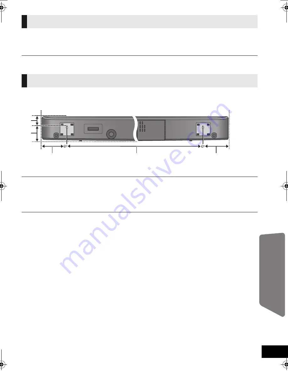
Use the measurements indicated below to identify the screwing positions on
the wall.
A
36 mm (1
13
/
32
q
)
B
72 mm (2
27
/
32
q
)
C
108.5 mm (4
9
/
32
q
)
D
812 mm (31
31
/
32
q
)
≥
Position the unit with at least 20 mm (
25
/
32
q
) of space above the unit and 100 mm (3
15
/
16
q
) on either side of the unit. If not, it
will not be possible to attach the unit to the wall.
≥
Be sure that there is enough space above the unit and that the screw hole positions are level with each other before
drilling into the wall.
≥
Be sure to use a spirit level to ensure that both screwing positions are horizontal to each other.
5
Checking the strength of the installation location.
≥
Check the wall strength at the 2 screwing positions. If the strength at any of these positions is lacking,
provide sufficient reinforcement.
j
The position in the wall where the screw is to be attached should be capable of supporting over
20 k
g
(44.1 lbs).
Connections
Placement
SCHTB500PP_RQTX1179-Y.book Page 27 Friday, June 18, 2010 10:07 AM


