background image

14 

2.7 Application Standard & Limit (For R22, R407C and R410A) 

The following requirements apply to vertical type hermetic scroll compressors: 

Standard:

    Applicable to ordinary conditions in Japan JIS B8616 or standards relative to JIS B8616, such 

as standard rating conditions, maximum operating conditions, low temperature conditions, etc. 

Limit:   

Applicable to transitional brief period, such as starting and beginning of defrost mode. 

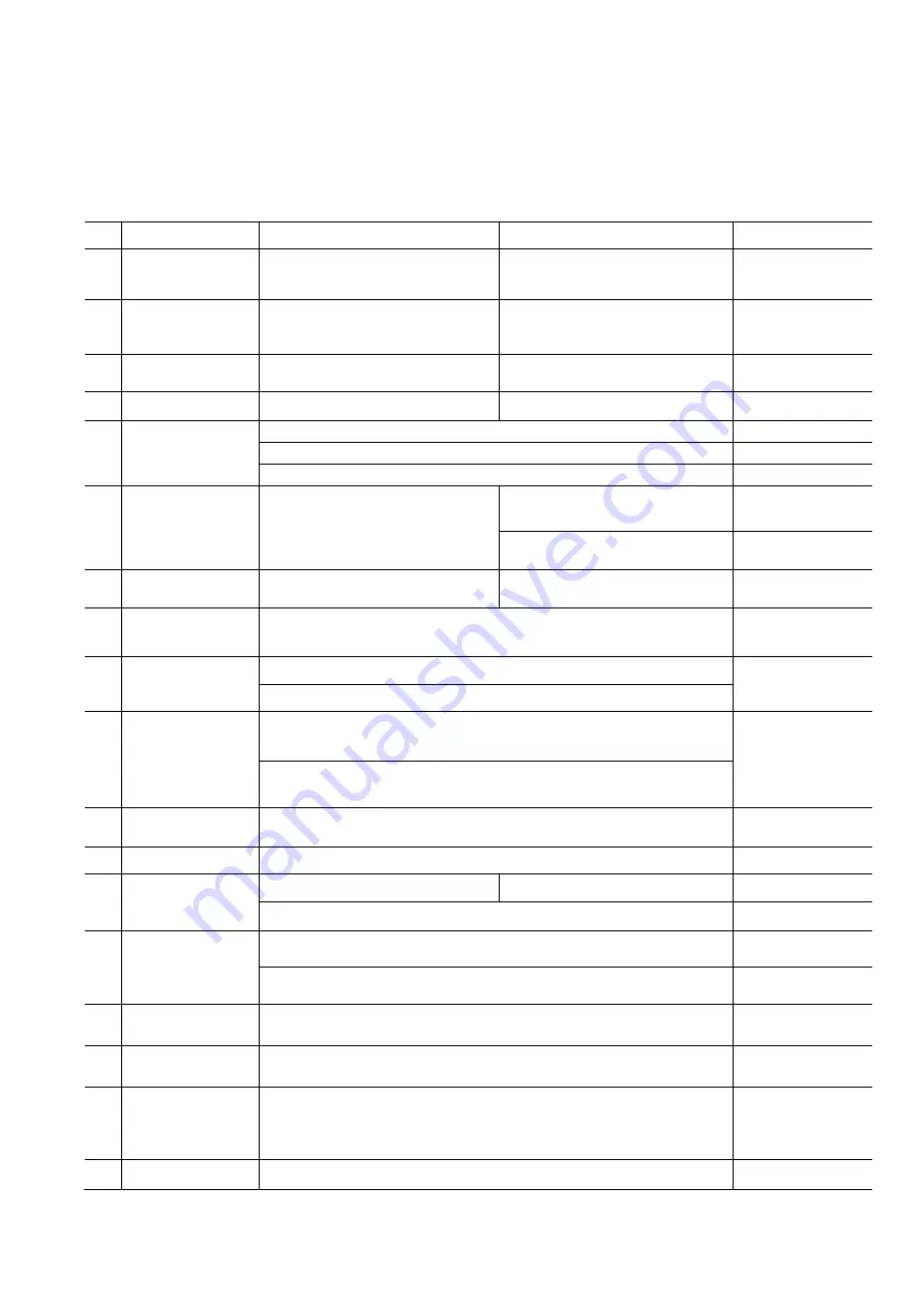
Table 2-6 

No. 

Item 

Standard 

Limit 

Note 

Evaporating  Temp. 
Range 

-15~12

(5

54 °F) 

-25~15

(-13

59 °F) 


Condensing  Temp. 
Range 

30~65

(86

149 °F) 

68

(155 °F) 

65

(149 °F) max. for R407C/R410A 


3  Compression Ratio 

2 ~ 6 

10   

(8 max. for 

R407C/R410A)


4  Winding Temp. 

115

(240 °F) Max. 

125

(257 °F) 


5  Shell Bottom Temp. 

90

(194 °F) Max.   


  Evaporating Temp. + 12K(21 °F) Min.   

Operating 

Ambient Temp. + 11K(20 °F) Min. 

Not Operating 

Discharge Gas 
Temp. 

115

(240 °F) Max. 

130

( 266°F) Max. for C-SB 

Within  10cm(4in.)  of 
the discharge fitting 

135

( 275°F) Max. for C-SC 

Inside  of  the  well  pile 
on the top of comp. 

7  Suction Gas Temp. 

Superheat: 5K(10 °F) Min. 

No excessive noise 

Items  4,5,6  and  14 
shall be kept. 

8  Running Voltage 

Within ±10% of the rated voltage 

Voltage  at  comp. 

terminals 

9  Starting Voltage 

Three Phase Models:    85% of the rated voltage min.   

Voltage at comp. 
terminals 

Single Phase Models:    90% of the rated voltage min. 

10  On/Off Period 

On Period: Until the oil level returns to the center of the lower 
bearing 

For at least 7 
minutes -on/3 
minutes-off is 
recommendable 

Off Period: Until balance of high and low pressure is obtained 

11  Refrigerant Charge 

Oil/Refrigerant(wt.)

0.35 

(Specific gravity of the Oil: SAY56T: 0.92; FV68S: 0.94) 


12  Life Time 

200,000 cycle 


13  Minimum Oil Level 

C-SB: Center of the lower bearing C-SB:Bottom of the lower bearing  

C-SC: No less then 70% of the initial oil charge 


14 

Abnormal  Pressure 
Rise/Drop 

Pressure Rise: see the Table 2-5 

By high pressure 
switch 

Pressure Drop: see the Table 2-4 

By low pressure 
switch 

15 

Copper Piping 
Stress 

Start/Shutdown: 34.32N/mm

2

 Max. 


Run: 12.26N/mm

Max. 


15 

System Moisture 
Level 

200ppm Max. 


16 

System 
Uncondensable 
Gas Level 

1 Vol.% Max. 

Residual Oxygen 0.1 Vol.% Max. 

24 hrs. after 
vacuuming: 
1.01kPa (0.15 psig) 
Max. 

17  Tilt 

5

Deg.Max. 


* Operation beyond the above limits must be approved by PAPCDL. 

Summary of Contents for SCROLL C-SB Series

Page 1: ...Ver 201909 Scroll Compressors Application Manual Panasonic Appliances Compressor Dalian Co Ltd ...

Page 2: ...tions 10 2 6 Protection Devices 10 2 7 Application Standard Limit For R22 R407C and R410A 14 2 8 Compressor Selection Table 15 2 9 System Test Data Table 16 3 0 Assembly and Manufacturing Process Considerations 19 3 1 Removing Rubber Plug 19 3 2 Compressor Mounting 19 3 3 Residual Moisture 19 3 4 Tube Brazing 19 3 5 Leakage Test 22 3 6 Evacuation 22 3 7 Refrigerant Charge 22 3 8 Wiring Connections...

Page 3: ...ze grounded connection Disconnect all input power before servicing Install the cover of terminal box before energized EXPLOSION OR FIRE HAZARD Remove the refrigerant before brazing operation Do not compress air or energize the compressor under vacuumed condition Use only approved refrigerants and refrigeration oil PERSONAL INJURY Personal safety equipment must be used BURN HAZARD Do not touch the ...

Page 4: ...ump assembly consists of fixed scroll and orbiting scroll and Oldham ring Orbiting scroll rotates on the surface of the main frame Figure 1 1 C SB Scroll Compressor Components See a cutaway view of C SB series compressor in Figure1 1 Discharge Tube Internal linebreak Bearing Plate Motor Main Frame Suction Tube Crankshaft Fixed Scroll Orbiting Scroll Check Valve Prevents reverse rotation at shutdow...

Page 5: ...on the main frame Figure 1 2 C SC Scroll Compressor Components See a cutaway view of C SC series compressor in Figure1 2 Internal linebreak Bearing Plate Motor Suction Tube Discharge Tube Crankshaft Fixed Scroll Orbiting Scroll Main Frame Suction Screen Oil SAY56T R22 FV68S HFCs Check Valves Prevent reverse rotation at shutdown Ball Bearing Heavy duty ball bearing Tip Seal of PPS resin Almost perf...

Page 6: ... as the scrolls rotate approximately one revolution Second orbit During the COMPRESSION process the gas is further compressed towards the center of the scroll elements to an intermediate pressure Third orbit In the DISCHARGE orbit the gas is further compressed to discharge pressure and then exits at the center through the discharge port With a three step simultaneous process of suction compression...

Page 7: ...pe of refrigerant oil is specially designed for certain types of refrigerant and operating conditions if additional oil charge is added in the field Only specified oil should be used Table 1 2 Type of Oil Refrigerant R22 R407C R410A R134a Oil Model SAY56T FV68S FV68S FV68S Oil Type Mineral Polyvinyl Ether PVE Polyvinyl Ether PVE Polyvinyl Ether PVE 1 4 2 Functions of Refrigerant Oil 1 Lubricate th...

Page 8: ...Pressure Higher a c Same OK Lower d b Note Higher The tested pressure is higher than recommended pressure Lower The tested pressure is lower than recommended pressure Same The tested pressure is approximately same as recommended pressure a Too big of compressor size b Too small of compressor size c Too high of dry bulb temperature in the condenser side Excessive refrigerant has charged in the syst...

Page 9: ...iquid refrigerant being sucked into compressor The suction accumulator used in the system should at least meet the requirements as follow 1 The size of the accumulator must be greater than 60 total refrigerant volume 2 To ensure well oil return a φ1 5 mm orifice is necessary in the suction accumulator 3 Filter mesh must be used to prevent orifice being blocked when orifice is smaller than φ2 0 mm ...

Page 10: ... Starting Voltage The voltage applied to compressor terminals when compressor is being started When compressor is starting the big starting current will cause the drop of voltage It will be very hard to start compressor if the starting voltage is too low c Running Voltage The line voltage applied to compressor terminals when compressor is running stably This running voltage is a little lower than ...

Page 11: ... 2 0 2 0 2 0 3 5 5 5 8 0 2 0 30max 3 5 5 5 14 0 40max 3 5 5 5 8 0 50max 8 0 14 0 22 0 60max 5 5 70max 3 5 8 0 14 0 3 5 80max 22 0 30 0 90max 14 0 100max 8 0 38 0 110max 120max 5 5 22 0 30 0 140max 14 0 50 0 5 5 160max 22 0 180max 38 0 60 0 8 0 200max 8 0 30 0 220max 50 0 80 0 240max 14 0 CAUTION OF GROUNDING The internal motor protector cannot protect the compressor against all possible failures P...

Page 12: ... until the internal linebreak cycles the compressor off After tripping the linebreak the compressor will operate in the correct direction when power is restored During powered reverse rotation the compressor will sound much louder than during normal operation To prevent this situation an anti short cycle timer of 3 minutes off 7 minutes on duration is recommended This will allow the compressor to ...

Page 13: ...n the system control unit is necessary in preventing three phases compressor from running in the reverse rotational direction 2 Discharge Gas Thermostat The discharge temperature will rise rapidly if the compressor is running under the overload conditions or lack of refrigerant conditions The maximum discharge temperature should be maintained by a discharge thermostat For the C SB series it is loc...

Page 14: ...tion of discharge thermostat or motor protector when the large amount of refrigerant leaks in the short time Do not operate the compressor in exceeding 30 seconds when running under 0 03MPa G 4 Crankcase Heater The refrigerant is usually gathering in coldest point within the system during OFF cycle and the compressor might become the right one where most of liquid refrigerant centralized The liqui...

Page 15: ...pressors require a high pressure switch in order to protect the compressor during blocked fan or fan failure conditions The recommended settings are shown in Table 2 5 Table 2 5 High Pressure Switch Setting Refrigerant Cut Off setting R22 435 psig 3 0MPa G R407C 464 psig 3 2MPa G R410A 602 psig 4 15MPa G R134a 348 psig 2 4MPa G Bottom Case Crankcase Heater ...

Page 16: ... F Min No excessive noise Items 4 5 6 and 14 shall be kept 8 Running Voltage Within 10 of the rated voltage Voltage at comp terminals 9 Starting Voltage Three Phase Models 85 of the rated voltage min Voltage at comp terminals Single Phase Models 90 of the rated voltage min 10 On Off Period On Period Until the oil level returns to the center of the lower bearing For at least 7 minutes on 3 minutes ...

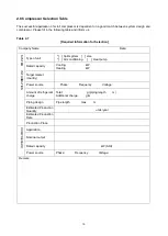
Page 17: ...TEM INFORMATION Type of unit Split system else Air conditioning Heat pump Rated capacity Cooling kW Heating kW Target market country Power source Phase Frequency Voltage Amount of refrigerant charge Total g piping length m Additional charge g m Piping design Pipe length max m Estimated Production Quantity units year Estimated Production Date Production Place COMPRESSOR Application Nominal output R...

Page 18: ...door Outdoor Cooling DB WB DB WB or Water Inlet Outlet Heating DB WB DB WB or Water Inlet Outlet 2 Table 2 9 Performance data Item Cooling Heating Minimum Voltage Rated Voltage Maximum Voltage Minimum Voltage Rated Voltage Maximum Voltage Voltage V Compressor input W Compressor Current A Motor Winding Temperature Compressor discharge gas temp Compressor suction gas temp Compressor shell bottom tem...

Page 19: ...ooling Heating Minimum Voltage Rated Voltage Maximum Voltage Minimum Voltage Rated Voltage Maximum Voltage Voltage V Compressor input W Compressor Current A Motor Winding Temperature Compressor discharge gas temp Compressor suction gas temp Compressor shell bottom temp Condensing Temperature Evaporating Temperature Temp before expansive valve High Side Pressure MPa G Low Side Pressure MPa G Remark...

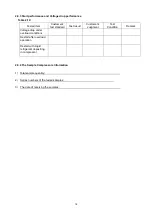
Page 20: ...tal sample quantity 2 Series numbers of the tested samples 3 The date of receiving the samples Tested item Customer s test standard Test result Customer s Judgment Test Condition Remark Voltage drop under overload conditions Restart after overload operation Restart with liquid refrigerant depositing in compressor ...

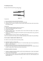
Page 21: ... heard when removing rubber plugs 3 2 Compressor Mounting Please use the mounting accessories grommets and sleeves that are supplied or specified by Dalian Panasonic as shown in Figure 3 1 1 Mounting Grommet 2 Mounting Sleeve Figure 3 1 Mounting Parts for C SB 3 3 Residual Moisture System residual moisture level should be kept less than 200ppm for C SB models and 500ppm for C SC models Normally if...

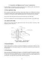
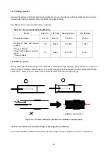
Page 22: ...er to Steel Steel with copper coated to steel Steel to Steel 45 BAg 1 620 760 Z 3261 3 4 2 Nitrogen purge During brazing the system piping to the compressor a Nitrogen purge with high purity 99 8 min must be used to prevent oxidation contamination The nitrogen purge cannot be stopped until the piping temperature below 200 See Figure 3 2 below for recommended flow method of nitrogen purge oxidation...

Page 23: ...ing prior to assembly c Apply heat to Area 1 moving the torch up down and around the tube in order to heat it evenly It will become dull orange in color d Move the torch to area 2 until it reaches dull orange in color and heat that area evenly e Add braze material to the joint while moving the torch around the joint to flow braze material evenly around the circumference f After braze material flow...

Page 24: ... confirm the vacuum degree of the system after removing the vacuum pump from the system Sufficient vacuum degree means 30 seconds after removing the vacuum pump below 1 0Torr 24 hours after removing the vacuum pump below 7 6Torr Please select proper size of vacuum pump according to the above vacuum degree requirements Do not use compressor as a vacuum pump and NEVER energize the compressor under v...

Page 25: ...d with the appropriate sequence As showed in wiring diagram the line phases R L1 S L2 and T L3 should be connected to terminals U V and W respectively Spade terminals type Screw terminals type Figure 3 4 Compressor Terminal 3 9 Terminal cover and clip The terminal cover and clip should be installed prior to operation of the compressor To ensure the cover is properly installed a double check should...

Page 26: ...e compressor 3 12 2 System Evacuation When evacuating a compressor in the field it is extremely important to use a vacuum manifold set with at least 2 vacuum lines connected to the system One line connected to the high side and the other connected to the low side of the system This procedure is necessary to ensure the system is completely evacuated since the scroll sets can seal under some non ene...

Page 27: ...0 Do not overheat the joint A cherry red color indicates overheating and can weaken the joint and fittings 3 12 5 Compressor Replacement for Motor Burn Out If a motor burn out is present follow the procedure as below 1 Evacuate the system per section 3 12 2 2 Remove the compressor as outlined in sections 3 12 3 and then follow proper clean out procedures as detailed in system instructions 3 Replac...

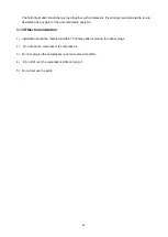
Page 28: ...ble for the accurate failure analysis 3 13 Other Consideration 1 Installation should be completed within 15 minutes after removing the rubber plugs 2 Do not use the compressor to compress air 3 Do not energize the compressor under vacuumed condition 4 Do not tilt over the compressor while carrying it 5 Do not remove the paint ...

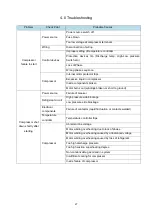
Page 29: ... out windings broken or short to ground Compressor shut down shortly after starting Power source Failure of breaker Refrigerant circuit High pressure side blockage Low pressure side blockage Electrical components Failure of contactor rapid fluctuation or contacts welded Temperature controller Temperature controller trips Compressor Abnormal line voltage Motor winding overheating due to lack of pha...

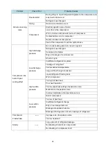
Page 30: ...or blockage of condenser coil Short air cycle Low discharge pressure Insufficient refrigerant in system Leakage of refrigerant Too low ambient temperature Large air flow through condenser Liquid refrigerant flooding back Worn compressor High suction pressure Too high of heat load Poor heat insulation Too low superheat setting of expansion valve Malfunction of expansion valve Incorrect installation...

Page 31: ...essor from reverse rotation due to the external wrong wiring into A C system 2 See Table 5 1 for judgments on reverse rotation of compressor Table 5 1 Judgments on reversal rotation of compressor Item Normal Rotation Reverse Rotation Discharge Tube Temp Increasing rapidly No obvious changes Suction Tube Temp Decline Slightly increasing Discharge Pressure Increasing rapidly No obvious changes Sucti...

Page 32: ...tart 4 Notice in field application On a field application when the internal motor protector has tripped the compressor will stop while each of 3 terminals is still energized to which either the customer or serviceman may regard the compressor as fail down Therefore the above mentioned situation should be taken into consideration ...

Reviews: