21
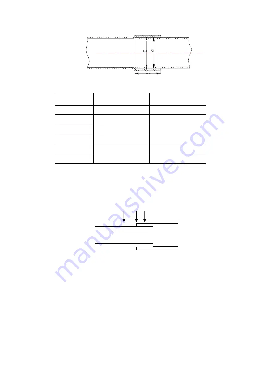
Table 3-2 The clearance and length
Piping
O.D.(mm)
Minimum Insertion
Length L1 (mm)
Clearance
D-d (mm)
5~8
6
0.05~0.35
8~12
7
0.05~0.35
12~16
8
0.05~0.45
16~25
10
0.05~0.45
25~35
12
0.05~0.55
35~45
14
0.05~0.55
3.4.4 Brazing Procedures
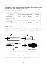
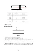
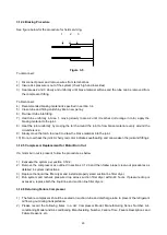
See Figure 3-3 for brazing area.
1 2 3
Figure 3-3
a)
A double-tipped torch is recommended during brazing;
b)
Clean the compressor tubing and system piping prior to assembly;
c)
Apply heat to Area 1, moving the torch up, down and around the tube in order to heat it evenly. It will
become dull orange in color.
d)
Move the torch to area 2 until it reaches dull orange in color and heat that area evenly.
e)
Add braze material to the joint while moving the torch around the joint to flow braze material evenly
around the circumference.
f)
After braze material flows around the joint, move to area 3, to draw the braze material into the joint. The
time spent heating area 3 should be minimal, to keep excess braze material from entering the compressor.


