S-7
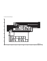
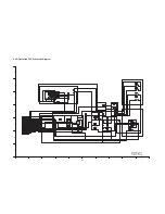
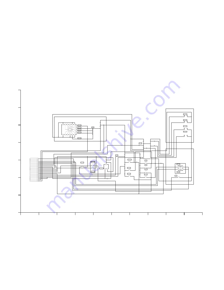
S4.5. Operation FPC Schematic Diagram
R2521
5600
R2520
2700
R2522
18K
R2513
2700
R2509
5600
R2502
47K
47K
R2501
R2512
10K
R2507
10K
18K
R2515
R2514
5600
R2510
18K
2700
R2508
R2518
10K
47K
R2505
R2506
47K
R2551
0[22]
R2555
0
R2554
0
R2552 0
R2553
0[22]
S2509
EVQP6FB35
S2508
EVQP6FB35
S2506
EVQP6FB35
S2507
EVQP6FB35
S2505
EVQP6FB35
S2516
EVQP6FB35
S2510
EVQP6FB35
S2513
EVQP6FB35
S2514
EVQP6FB35
S2512
EVQP6FB35
S2511
EVQP6FB35
CL2503 CL2504
CL2507 CL2508
CL2505 CL2506
CL2501 CL2502
3
4
13
5
14
1
12
11
16
2
15
10
C
C
8
9
7
6
K0G177A00002
S2515
1
9
7
5
3
2
4
6
8
17
18
13
14
11
10
12
16
15
20
19
FT2501
4
1
2
3
D2501
B3ABB0000033
1
3
2
IC2501
B4ZZ00000012
C2506
F1H0J106A009
PW_CPU_VDD
PW_RTC3R1V
P_PLAY
POWER_SW
M_PLAY
M_REC
P_REC
LEFT (1.32V)
(1.32V)
(1.32V)
KEY3
(0V)
(0V)
(0V)
(0V)
DELETE
(0.62V)
(0.62V)
(0.62V)
(2.10V)
KEY1
(P_ON:OPEN P_OFF:CLOSE)
KEY2
MENU
(2.1V)
(2.1V)
ENTER
ZOOM
UP
DOWN
RIGHT
(RED)
POWER
STANDBY (GREEN)
SS
(0.97V)
WIDE_LOW
WIDE_HI
TELE_LOW (1.93V)
GND
GND
GND
GND
GND
OUT
LCD_OPEN
LCD_OPEN
VCC
(OPEN:H CLOSE:L)
(0.4mm)
(0.5mm)
(0.5mm)
AUTO_SW
POWER_LED
PW_CPU_VDD=2.9V(TYP)
PW_RTC3R1V=3.1V(TYP)
MF_SW
POWER SW
AD_KEY3
GND(LED)
(UE)
CARD_LED
AD_KEY1(MODE)
PW_CPU_VDD
PW_CPU_VDD
AD_KEY2(CROSS)
ZOOM_AD
S/S_SW
STANDBY_LED
PW_RTC3R1V
AF/MF
TELE_HI (2.9V)
WATER
SDR-SW20 Series
Operation FPC
Schematic Diagram
10
9
8
7
6
5
4
3
2
1
G
F
E
D
C
B
A
Summary of Contents for SDR-SW20E
Page 9: ...9 4 Specifications For P PC PL areas For other areas ...
Page 10: ...10 ...
Page 11: ...11 5 Location of Controls and Components ...
Page 16: ...16 8 1 Disassembly Flow Chart 8 2 PCB Location ...
Page 18: ...18 8 3 1 Removal of the Front case unit Fig D1 8 3 2 Removal of the Tripod piece Fig D2 ...
Page 20: ...20 8 3 6 Removal of the Side case L unit Fig D7 Fig D8 ...
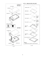
Page 24: ...24 Fig D20 8 3 15 Removal of the LCD hinge unit and Monitor P C B Fig D21 ...
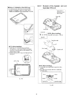
Page 25: ...25 Fig D22 8 3 16 Removal of the LCD panel Fig D23 ...
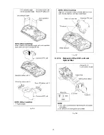
Page 26: ...26 Fig D24 8 3 17 Removal of the Speaker unit and Operation FPC unit Fig D25 ...
Page 27: ...27 Fig D26 Fig D27 8 3 18 Removal of the CCD unit and Optical filter Fig D28 ...

