


SF4C Safety light curtain
2.7 Wiring Examples
51
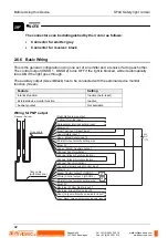
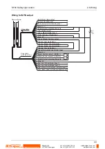
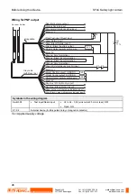
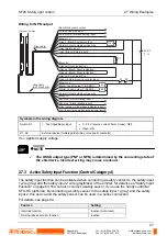
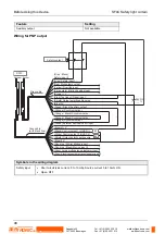
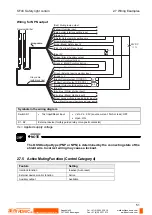
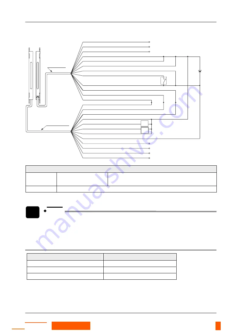
Wiring for NPN output
K1
K2
S1
+
24V DC
%
-
+10
-15
(Brown) + V
(Pink) Test input / Reset input
(Pale purple) Interlock setting input
(Yellow) Override input
(Red) Muting lamp output
(
G
reen / Black) Auxiliary output
(Gray) Safety input 1
(Gray / Black) Safety input 2
(Shield) Output polarity setting wire
(Blue) 0V
(Orange) Synchroni
(Orange / Black) Synchronization -
(Orange / Black) Synchronization -
(Orange) Synchroni
(Brown) + V
(Gray) Large multi-purpose indicator input 1
(Sky-blue / White) Muting input 1
(
G
reen) External device monitor input
(Black) Control output 1 (OSSD 1)
(White) Control output 2 (OSSD 2)
(Shield) Output polarity setting wire
(Blue) 0V
(Gray / Black) Large multi-purpose indicator input 2
(Sky-blue / Black) Muting input 2
Gray cable
Emitter
Receiver
Gray cable
(with black line)
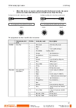
Symbols in the wiring diagram
Switch S1
•
Test input/Reset input
•
Vs to Vs - 2.5V (source current: 5mA or less): OFF
•
Open: ON
K1, K2
External device (forcibly guided relay or magnetic contactor)
Vs = Applied supply voltage
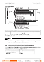
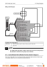
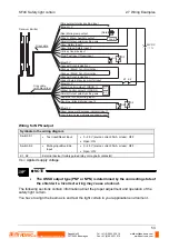
NOTE
The OSSD output type (PNP or NPN) is determined by the connecting state of the
shield wire. Incorrect wiring may cause a lockout.
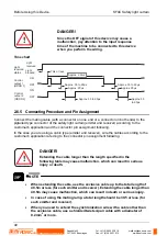
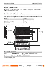
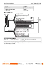
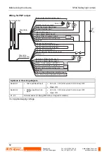
2.7.5 Active Muting Function (Control Category 4)
Feature
Setting
Interlock function
Inactive (Auto reset)
External device monitor function
Active
Auxiliary output
Available
Rugghölzli 2
CH - 5453 Busslingen
Tel. +41 (0)56 222 38 18
Fax +41 (0)56 222 10 12
mailbox@sentronic.com
www.sentronic.com
Produkte, Support und Service
SENTRONIC
AG


