SF4C Safety light curtain
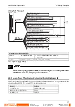
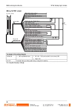
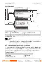
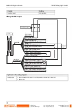
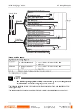
2.7 Wiring Examples
55
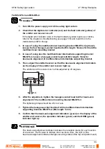
For MS-SFC-3 and MS-SFC-4:
1.
2.
3.
Procedure
1. Turn ON the power supply unit of the safety light curtain
2. Check that the digital error indicator (red) and the fault indicator (yellow) of
the emitter and receiver are off
If the digital error indicator (red) or the fault indicator (yellow) lights up or blinks,
refer to the chapter on troubleshooting (see page 103) and report this to the
maintenance staff in charge.
3. In case of using the multifunctional mounting bracket MS-SFC-3 (optional),
loosen the four hexagon-socket head bolts (M3, length: 5mm) which hold the
multifunctional mounting bracket
4. In case of using also the multifunctional intermediate supporting bracket
MS-SFC-4, loosen a hexagon-socket head bolt (M3, length: 5mm) for
beam-axis alignment of multifunctional intermediate supporting bracket
5. Then, adjust the emitter/receiver so that the beam-axis alignment indicators
on the display of the emitter and receiver light up
The emitter and the receiver can be fine-adjusted by ±5 degrees.
±5
6. After the adjustment, tighten the hexagon-socket head bolt for beam-axis
alignment of the multifunctional mounting bracket MS-SFC-3
The tightening torque should be 2N·m or less.
7. Tighten the hexagon-socket head bolt of the multifunctional intermediate
supporting brackets MS-SFC-4 (M3, length: 5 mm)
8. Confirm that the beam-axis alignment indicators (green) on the display of the
emitter and receiver, the operation indicator (green) and the OSSD (green)
indicator light up
REFERENCE
The beam-axis alignment indicator indicates the reception status for each section
of a receiver. The receiver is divided into 4 sections. Also, the A (D) of the
beam-axis alignment indicates the light-receiving status of the top end (bottom end)
Rugghölzli 2
CH - 5453 Busslingen
Tel. +41 (0)56 222 38 18
Fax +41 (0)56 222 10 12
mailbox@sentronic.com
www.sentronic.com
Produkte, Support und Service
SENTRONIC
AG

