background image

Operation 


SF4C Safety light curtain 

88 

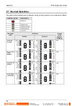
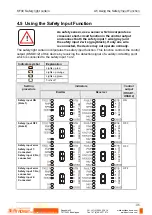
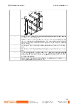
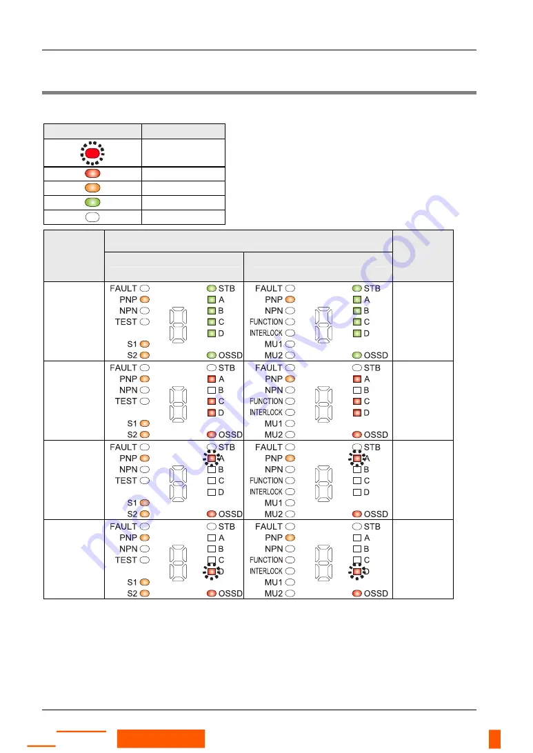
4.1 Normal Operation 

The status of the emitter/receiver indicators during normal operation is as described as follows. 


Indicator symbol 

Explanation 


Blinks red 


Lights up red 


Lights up orange 


Lights up green 


Turns off 


Indicators 

Reception 

state 

Emitter 

Receiver 

Control 

output 

(OSSD 1, 

OSSD 2)


All beams 
received 

RECEPTION

RECEPTION

ON 

One or more 
beams 
blocked 

RECEPTION

RECEPTION

OFF 

Only top end 
blocked 

RECEPTION

RECEPTION

OFF 

Only bottom 
end blocked 

RECEPTION


RECEPTION

OFF 

Rugghölzli 2

CH - 5453 Busslingen

Tel. +41 (0)56 222 38 18

Fax +41 (0)56 222 10 12

mailbox@sentronic.com

www.sentronic.com

Produkte, Support und Service

SENTRONIC

AG

Summary of Contents for SF4C Series

Page 1: ...sAFETY LIGHT CURTAIN SF4C Instruction Manual Rugghölzli 2 CH 5453 Busslingen Tel 41 0 56 222 38 18 Fax 41 0 56 222 10 12 mailbox sentronic com www sentronic com Produkte Support und Service SENTRONICAG ...

Page 2: ...nsequential damage resulting from any defect in the product or its documentation even if advised of the possibility of such damages We invite your comments on this manual Please e mail us at tech doc eu pewg panasonic com Please direct support matters and technical questions to your local Panasonic representative LIMITED WARRANTY If physical defects caused by distribution are found PEWEU will repl...

Page 3: ... so may result in injury or significant damage to instruments or their contents e g data NOTE Contains important additional information EXAMPLE Contains an illustrative example of the previous text section 1 2 3 Procedure Indicates that a step by step procedure follows REFERENCE Indicates where you can find additional information on the subject at hand Rugghölzli 2 CH 5453 Busslingen Tel 41 0 56 2...

Page 4: ...2 4 2 Safety Distance 16 2 4 2 1 Calculation Example for Europe 18 2 4 2 2 Calculation Example for US 20 2 4 3 Influence of Reflective Surface 22 2 4 4 Device Placement 22 2 5 Mounting 25 2 5 1 Mounting with Standard Mounting Bracket 25 2 5 2 Mounting with Multifunctional Mounting Bracket MS SFC 3 optional 26 2 5 3 Dead Zoneless Mounting 28 2 5 4 Mounting the Intermediate Supporting Bracket MS SFC...

Page 5: ...rol Category 4 51 2 7 6 Beam axis Alignment 54 2 7 7 Operation Test 56 3 Functions 59 3 1 Self Diagnosis Function 60 3 2 Interlock Function 61 3 3 Test Input Function 62 3 4 Safety Input Function 63 3 4 1 Serial Connection and Response Time 64 3 4 2 Wiring Example for Safety Contact 65 3 4 3 Wiring Example for Safety Sensor 66 3 5 Large Multi purpose Indicator Function 70 3 5 1 Wiring Example of t...

Page 6: ...98 5 2 Periodic Inspection Checklist Every Six Months 100 5 3 Inspection after Maintenance 101 6 Troubleshooting 103 6 1 Emitter Related Problems 104 6 1 1 Indicator Section of the Emitter 104 6 1 2 All Indicators Are OFF 104 6 1 3 Digital Error Indicator Red Lights Up or Blinks 104 6 1 4 Setting Indicator Lights Up 106 6 1 5 Test input Indicator Orange Lights Up 106 6 1 6 Operation Indicator Rema...

Page 7: ...or 118 7 3 2 Brackets 118 7 3 2 1 Standard Mounting Bracket MS SFC 1 118 7 3 2 2 NA2_N Compatible Mounting Bracket 118 7 3 2 3 Multifunctional Mounting Bracket MS SFC 3 119 7 3 2 4 Mounting Bracket MS SFC 4 119 7 3 3 Protective Metal Case 120 7 3 4 Handy Controller 120 7 3 5 Test Rod 121 8 Dimensions 123 8 1 Mounting Dimensions 124 8 1 1 Centered Mounting with Standard Mounting Brackets 124 8 1 2 ...

Page 8: ...g Bracket MS SFC 3 130 8 2 4 Multifunctional Mounting Bracket MS SFC 3 without Dead Zone 130 8 2 5 Multifunctional Intermediate Supporting Bracket MS SFC 4 131 8 2 6 Protective Metal Case 131 9 Glossary of Terms 133 10 Index 135 Rugghölzli 2 CH 5453 Busslingen Tel 41 0 56 222 38 18 Fax 41 0 56 222 10 12 mailbox sentronic com www sentronic com Produkte Support und Service SENTRONICAG ...

Page 9: ...Chapter 1 Introduction Rugghölzli 2 CH 5453 Busslingen Tel 41 0 56 222 38 18 Fax 41 0 56 222 10 12 mailbox sentronic com www sentronic com Produkte Support und Service SENTRONICAG ...

Page 10: ...structions for installation and maintenance contained in the instruction manual are followed Whether this device functions as intended and systems including the SF4C comply with safety regulations depend on the appropriateness of the application installation maintenance and operation The machine designer installer employer and operator are solely responsible for these items Engineer The engineer m...

Page 11: ...r regional security committees No matter what kind of equipment you use the device with follow the safety regulations in regard to appropriate usage mounting installation operation and maintenance Use the safety light curtain by installing suitable protective equipment as a countermeasure for failure damage or malfunction of this device Before using this light curtain check whether it performs pro...

Page 12: ...nect the sets and if necessary install some barriers so that mutual interference does not occur Do not use any reflection type or recursive reflection type arrangement Equipment in which this device is installed When the safety light curtain is used in the PSDI see page 134 mode an appropriate control circuit must be configured between this device and the machinery For details be sure to refer to ...

Page 13: ...urer the safety light curtain may fail to detect properly which may result in death or serious body injury The device must be inspected periodically by an engineer with the required knowledge When you have adjusted or maintained the SF4C test the device following the procedure specified in the maintenance chapter see page 97 before you switch the system back on Clean this device with a clean cloth...

Page 14: ... ANSI B11 1 to B11 19 ANSI RIA 15 06 NOTE Conformity to JIS OSHA and ANSI for this device has been evaluated by us This device conforms to the EMC directive and the Machinery directive The CE mark indicates that this product conforms to the EMC directive This device is certified by TÜV Süd The C CL US Listing Mark indicates compliance with both Canadian and U S requirements If you want to use this...

Page 15: ...Chapter 2 Before Using this Device Rugghölzli 2 CH 5453 Busslingen Tel 41 0 56 222 38 18 Fax 41 0 56 222 10 12 mailbox sentronic com www sentronic com Produkte Support und Service SENTRONICAG ...

Page 16: ...Check mark Number Package content 1 piece Sensor with 1 emitter and 1 receiver 1 piece Test rod 1 piece Instruction manual this manual Rugghölzli 2 CH 5453 Busslingen Tel 41 0 56 222 38 18 Fax 41 0 56 222 10 12 mailbox sentronic com www sentronic com Produkte Support und Service SENTRONICAG ...

Page 17: ...1 2 is a PNP NPN output switching type Large multi purpose indicators red green which are bright and easy to see are incorporated Each function can be set by using the handy controller SFC HC optional see page 84 For details of options see Options on page 117 Rugghölzli 2 CH 5453 Busslingen Tel 41 0 56 222 38 18 Fax 41 0 56 222 10 12 mailbox sentronic com www sentronic com Produkte Support und Ser...

Page 18: ...utput OSSD 1 OSSD 2 turns ON when the all beam channels receive light from the emitter and the control output OSSD 1 OSSD 2 turns OFF when one or more beam channels are blocked Except when using the muting function see note Beam channel The light emitting elements of the emitter and the light receiving elements of the receiver are placed at the intervals of 20mm Standard mounting bracket MS SFC 1 ...

Page 19: ...peration of Large Multi Purpose Indicator on page 14 Incident light intensity indicator green orange STB Lights up in green when stable light is received Lights up in orange when unstable light is received Turns OFF when light is blocked Note 2 A When the control output OSSD 1 2 is ON lights up green When the top block receives light lights up red When the top end receives light blinks red B When ...

Page 20: ...ve Turns OFF when the safety input 2 is inactive The description given in is marked on the sensor Receiver Function Description Large multi purpose indicator Note 1 Lights up in red when the large multi purpose indicator input is active Lights up in green when the large multi purpose indicator input is active Turns OFF when the input is inactive Incident light intensity indicator green orange STB ...

Page 21: ...ndicator INTERLOCK yellow Lights up when interlock is active Turns OFF when interlock is inactive Muting input 1 orange MU1 Lights up when the muting input 1 is active Turns off when the muting input 1 is inactive Muting input 2 indicator orange MU2 Lights up when the muting input 2 is active Turns off when the muting input 2 is inactive NOTE The operation of the large multi purpose indicator ligh...

Page 22: ... PNP output OFF PNP output ON ON OFF Active Inactive 0 Lights up red Lights up green 1 Blinks red Blinks green 2 Lights up red Blinks green 3 Blinks red Lights up green 4 Lights up red Blinks red 5 Blinks green Lights up green 6 Lights up green Lights up red Blinks green 7 Lights up red Blinks red Lights up green Blinks green REFERENCE Further information regarding the functionality of the handy c...

Page 23: ...r and the receiver The sensing height is determined by the number of beam channels The sensing range depends on the device type 0 1 to 3m Also remember that if the sensing range is less than 0 1m malfunction may occur due to the optical structure Sensing height sensing range and sensing area Sensing height Bottom Top The sensing height is the area between the line indicated in the top part and lin...

Page 24: ...ts of the machine If the safety distance is miscalculated or not sufficient the machine will not stop quickly enough when a human body or an object reaches the dangerous parts which may result in serious injury or death The safety distance is the minimum distance that must be maintained between the light curtain and the dangerous parts of the machine so that the machine can be stopped before a hum...

Page 25: ...tc for details of the calculation The max response time of the machine is from the point when the machine receives the halt signal from this device to the point when the dangerous part of the machine stops The max response time of the machine should be timed with the actual machine The minimum size of the objects to be detected by the safety light curtain varies depending on whether the floating b...

Page 26: ...he machine documentation or take a measurement using a special device called a brake monitor T TSF4C Response time of this device s Additional distance calculated from the minimum size of the object to be detected by the sensor mm C has to be 0 or more C 8 x d 14 C d Minimum object diameter mm 1 2 3 Procedure 1 Calculate the safety distance S with a velocity K 2 000mm s There are 3 possibilities 1...

Page 27: ... TSF4C 8 x d 14 2 000 x 0 1 0 007 8 x 25 14 302 As 302 matches possibility 2 listed above 302mm is the safety distance EXAMPLE Calculate the safety distance with the following values K 2 000mm s Tm 0 4s TSF4C 7ms d 25mm With these values the calculation is as follows S K x T C K x Tm TSF4C 8 x d 14 2 000 x 0 4 0 007 8 x 25 14 902 As 902 matches possibility 3 listed above recalculate the safety dis...

Page 28: ...sor mm C 850 mm Constant 2 4 2 2 Calculation Example for US he equation safety distance S is calculated in accordance with ANSI RIA B15 06 with the formula S K x Ts Tc TSF4C Tbm Dpf S Safety distance mm Minimum distance required between the sensing area surface and the dangerous parts of the machine K Intrusion velocity of operator s body or object The recommended value in OSHA is 63inch s 1 600mm...

Page 29: ...fer to the relevant standard for details EXAMPLE Calculate the safety distance with the following values TSF4C 7s d 0 985ich 20mm With these values the calculation is as follows S K x Ts Tc TSF4C Tbm Dpf 63 x Ta 0 014 3 4 x d 0 276 inch 63 x Ta 0 014 3 4 x 0 985 0 276 63 x Ta 63 x 0 007 3 4 x 0 709 63 x Ta 0 441 2 4106 63 x Ta 2 85inch In case this device is installed in a system with a maximum ha...

Page 30: ...or not to detect properly which may result in death or serious injury Install this device at a distance of at least 0 16m away from reflective surfaces such as metal walls floors ceilings workpieces covers panels or glass surfaces Side view Top view Reflective ceiling Emitter Receiver Sensing range Reflective floor 0 1 3m 0 16m 0 16m Reflective surface Emitter Receiver Sensing range 0 16m 0 1 3m 2...

Page 31: ...nterference occurs it can result in serious injury or death EXAMPLE 1 Install the emitters or the receivers back to back Receiver Receiver Emitter Emitter 2 Arrange the emitters and the receivers vertically on opposite sides Receiver Receiver Emitter Emitter 3 Arrange the emitters and the receivers horizontally on opposite sides Receiver Receiver Emitter Emitter 4 Install a barrier Receiver Barrie...

Page 32: ...res above are just examples of sensor placement If there are any questions or problems please contact our office Rugghölzli 2 CH 5453 Busslingen Tel 41 0 56 222 38 18 Fax 41 0 56 222 10 12 mailbox sentronic com www sentronic com Produkte Support und Service SENTRONICAG ...

Page 33: ...e could cause the wire to break The minimum bending radius of the cable is 6mm Mount the sensor accordingly Mount the emitter and the receiver at the same level and parallel to each other The effective aperture angle of this device is 2 5 or less for a sensing distance exceeding 3m Unless otherwise specified the mounting procedure is common for both emitters and receivers To prepare the mounting h...

Page 34: ...n three directions Standard mounting bracket MS SFC 1 Accessory M3 countersunk head screw with anti loosening agent length 4mm 4 Install the standard mounting brackets on the mounting surface with two hexagon socket head bolts M5 2 5 2 Mounting with Multifunctional Mounting Bracket MS SFC 3 optional The following procedure shows how to mount the safety light curtain with the multifunctional mounti...

Page 35: ...unctional mounting bracket using the M3 countersunk head screw with anti loosening agent length 4mm accessory of the multifunctional mounting bracket The tightening torque should be 0 3N m M3 countersunk head screw with anti loosening agent length 4mm Accessory of multifunctional mounting bracket Multifunctional mounting bracket MS SFC 3 optional Part B Part A Rugghölzli 2 CH 5453 Busslingen Tel 4...

Page 36: ...ead bolt NOTE SF4C H28 and SF4C H32 require the multifunctional intermediate supporting bracket MS SFC 4 optional see page 31 2 5 3 Dead Zoneless Mounting You can mount the safety light curtain with the multifunctional mounting bracket MS SFC 3 so that no dead zone exists follow this procedure Rugghölzli 2 CH 5453 Busslingen Tel 41 0 56 222 38 18 Fax 41 0 56 222 10 12 mailbox sentronic com www sen...

Page 37: ...orque should be 0 3N m M3 countersunk head screw with anti loosening agent length 4mm Accessory of multifunctional mounting bracket Multifunctional mounting bracket MS SFC 3 optional Part B Part A 3 Remove the two of the hexagon socket head bolts for beam axis alignment M3 length 5mm on part A Part A Part B Hexagon socket bolt for beam axis alignment 4 Separate part A from part B and change the di...

Page 38: ...acket on the mounting surface using either two hexagon head bolts M6 or four hexagon head bolts M4 SF4C SF4C Hexagon head bolts Hexagon head bolt NOTE SF4C H28 and SF4C H32 require the multifunctional intermediate supporting bracket MS SFC 4 optional see page 31 Rugghölzli 2 CH 5453 Busslingen Tel 41 0 56 222 38 18 Fax 41 0 56 222 10 12 mailbox sentronic com www sentronic com Produkte Support und ...

Page 39: ...dard mounting bracket MS SFC 1 is not attached at the safety light curtain otherwise loosen it 2 Slip on the multifunctional intermediate supporting bracket MS SFC 4 optional from the top or from the bottom of the device SF4C Multifunctional intermediate supporting bracket MS SFC 4 Optional Rugghölzli 2 CH 5453 Busslingen Tel 41 0 56 222 38 18 Fax 41 0 56 222 10 12 mailbox sentronic com www sentro...

Page 40: ...nal mounting bracket MS SFC 3 optional It cannot be mounted in combination with the standard mounting bracket 2 5 5 Mounting the Protective Metal Case If you want to mount the protective metal case follow this procedure 1 2 3 Procedure 1 Make sure that the standard mounting bracket MS SFC 1 accessory mounted to this device is fixed in the center 2 Slip on the protective metal case from the top of ...

Page 41: ...h the standard mounting bracket MS SFC 1 accessory It cannot be mounted in combination with the multifunctional mounting bracket MS SFC 3 optional When mounting the protective metal case MS SFCH optional to this device make sure that the standard mounting bracket MS SFC 1 accessory is mounted centered When the standard mounting bracket is mounted as dead zoneless mounting the protective metal case...

Page 42: ...ensure that dangerous performance caused by the earth failure cannot occur Failure to do so could cause jeopardize the system stop resulting in serious bodily injury or death Ground the 0V side PNP output 24V side NPN output to ensure that the output is not turned ON by accident due to an earth fault of the control output OSSD 1 OSSD 2 When this product is used in a situation where it has to confo...

Page 43: ...conform to the EMC Directive and Low Voltage Directive where CE certification is required The power supply unit must conform to CLASS 2 where UL cUL certification is required If the power supply conforms to the Low Voltage Directive and has an output of 100VA or less it is suitable The frame ground F G terminal must be connected to ground when using a commercially available switching regulator The...

Page 44: ...ization Orange Black Synchronization Orange Synchronization Brown V Gray Large multi purpose indicator input 1 Sky blue White Muting input 1 Green External device monitor input Black Control output 1 OSSD 1 White Control output 2 OSSD 2 Shield Output polarity setting wire Blue 0V Gray Black Large multi purpose indicator input 2 Sky blue Black Muting input 2 Main circuit Main circuit Internal circu...

Page 45: ...anual reset is activated Vs to Vs 3 5V sink current 5mA or less OFF Open ON When auto reset is activated Vs to Vs 3 5V sink current 5mA or less ON Open OFF Switch S2 Interlock setting input Override input Large multi purpose indicator input 1 2 Muting input 1 2 External device monitor input Vs to Vs 3 5 V sink current 5mA or less ON Open OFF K1 K2 External device forcibly guided relay or magnetic ...

Page 46: ...ization Orange Black Synchronization Orange Synchronization Brown V Gray Large multi purpose indicator input 1 Note 2 Sky blue White Muting input 1 Green External device monitor input Black Control output 1 OSSD 1 White Control output 2 OSSD 2 Shield Output polarity setting wire Blue 0V Gray Black Large multi purpose indicator input 2 Note 2 Sky blue Black Muting input 2 Users circuit Terminal No ...

Page 47: ...cator input 1 2 Muting input 1 2 External device monitor input Vs to Vs 2 5 V source current 5mA or less ON Open OFF K1 K2 External device forcibly guided relay or magnetic contactor Resistance A 3kΩ Resistance B 6 8kΩ Resistance C 470Ω Resistance D 47kΩ Condenser E Condenser F 0 47μF 0 1μF Vs Applied supply voltage 2 6 4 Output Signal during Self Diagnosis Since the receiver performs the self dia...

Page 48: ...wing In the case you are using a cable type emitter and receiver wire the cables according to the customer s application referring to the connector pin assignment following DANGER Extending the cable longer than the length specified in the following table may cause malfunction which can result in serious injury or death NOTE When extending the cable use the exclusive cable up to the total length o...

Page 49: ...t 5 Orange Synchronization 6 Orange Black Synchronization 7 Blue 0V 8 Shield Output polarity setting wire 9 Gray Safety input 1 10 Gray Black Safety input 2 11 Yellow Override input Emitter Gray Gray 12 Red Muting lamp output 1 White Control output 2 OSSD 2 2 Brown V 3 Black Control output 1 OSSD 1 4 Green External device monitor input 5 Orange Synchronization 6 Orange Black Synchronization 7 Blue...

Page 50: ...1 K2 10 15 24V DC Brown V Pink Test input Reset input Pale purple Interlock setting input Yellow Override input Red Muting lamp output Green Black Auxiliary output Gray Safety input 1 Gray Black Safety input 2 Shield Output polarity setting wire Blue 0V Orange Synchronization Orange Black Synchronization Orange Black Synchronization Orange Synchronization Brown V Gray Large multi purpose indicator...

Page 51: ...ion Orange Black Synchronization Orange Synchronization Brown V Gray Large multi purpose indicator input 1 Sky blue White Muting input 1 Green External device monitor input Black Control output 1 OSSD 1 White Control output 2 OSSD 2 Shield Output polarity setting wire Blue 0V Gray Black Large multi purpose indicator input 2 Sky blue Black Muting input 2 Gray cable Emitter Receiver Gray cable with ...

Page 52: ...Gray Safety input 1 Gray Black Safety input 2 Shield Output polarity setting wire Blue 0V Orange Synchronization Orange Black Synchronization Orange Black Synchronization Orange Synchronization Gray Large multi purpose indicator input 1 Sky blue White Muting input 1 Green External device monitor input Black Control output 1 OSSD 1 White Control output 2 OSSD 2 Shield Output polarity setting wire B...

Page 53: ...blue Black Muting input 2 Gray cable Emitter Receiver Gray cable with black line Load Symbols in the wiring diagram Switch S1 Test input Reset input 0 2 5V source current 5mA or less OFF Open ON K1 K2 External device forcibly guided relay or magnetic contactor Vs Applied supply voltage NOTE The OSSD output type PNP or NPN is determined by the connecting state of the shield wire Incorrect wiring ma...

Page 54: ...ator input 1 Sky blue White Muting input 1 Green External device monitor input Black Control output 1 OSSD 1 White Control output 2 OSSD 2 Shield Output polarity setting wire Blue 0V Gray Black Large multi purpose indicator input 2 Sky blue Black Muting input 2 Gray cable Emitter Receiver Gray cable with black line Load Symbols in the wiring diagram Switch S1 Test input Reset input Vs to Vs 3 5V s...

Page 55: ...et input 0 2 5V source current 5mA or less OFF Open ON K1 K2 External device forcibly guided relay or magnetic contactor Vs Applied supply voltage NOTE The OSSD output type PNP or NPN is determined by the connecting state of the shield wire Incorrect wiring may cause a lockout 2 7 3 Active Safety Input Function Control Category 4 The safety input function can be activated when connecting a safety ...

Page 56: ...range Synchronization Brown V Gray Large multi purpose indicator input 1 Sky blue White Muting input 1 Green External device monitor input Black Control output 1 OSSD 1 White Control output 2 OSSD 2 Shield Output polarity setting wire Blue 0V Gray Black Large multi purpose indicator input 2 Sky blue Black Muting input 2 Gray cable Emitter Receiver Gray cable with black line Safety contact Symbols ...

Page 57: ...utput polarity setting wire Blue 0V Gray Black Large multi purpose indicator input 2 Sky blue Black Muting input 2 Gray cable Gray cable with black line Safety contact SF4C Emitter Receiver Symbols in the wiring diagram Safety input Short circuit sink current 5 to 10mA Source current 5 to 10mA ON Open OFF NOTE The OSSD output type PNP or NPN is determined by the connecting state of the shield wire...

Page 58: ...n Orange Synchronization Brown V Gray Large multi purpose indicator input 1 Sky blue White Muting input 1 Green External device monitor input Black Control output 1 OSSD 1 White Control output 2 OSSD 2 Shield Output polarity setting wire Blue 0V Gray Black Large multi purpose indicator input 2 Sky blue Black Muting input 2 Gray cable Emitter Receiver Gray cable with black line Symbols in the wirin...

Page 59: ...larity setting wire Blue 0V Gray Black Large multi purpose indicator input 2 Sky blue Black Muting input 2 Gray cable Emitter Receiver Gray cable with black line Symbols in the wiring diagram Switch S1 Test input Reset input Vs to Vs 2 5V source current 5mA or less OFF Open ON K1 K2 External device forcibly guided relay or magnetic contactor Vs Applied supply voltage NOTE The OSSD output type PNP ...

Page 60: ...lack Control output 1 OSSD 1 White Control output 2 OSSD 2 Shield Output polarity setting wire Blue 0V Gray Black Large multi purpose indicator input 2 Sky blue Black Muting input 2 Gray cable Gray cable with black line Pale purple Interlock setting input Load Note 1 Emitter Receiver Symbols in the wiring diagram Switch S1 Test input Reset input Vs to Vs 3 5V sink current 5mA or less OFF Open ON S...

Page 61: ... cable Emitter Receiver Gray cable with black line Pale purple Interlock setting input Load Note Wiring for NPN output Symbols in the wiring diagram Switch S1 Test input Reset input 0 2 5V source current 5mA or less OFF Open ON Switch S2 Muting input Override input 0 2 5V source current 5mA or less OFF Open ON K1 K2 External device forcibly guided relay or magnetic contactor Vs Applied supply volt...

Page 62: ... staff in charge 3 In case of using the standard mounting bracket MS SFC 1 accessory loosen the hexagon socket head bolts M5 which holds the standard mounting bracket MS SFC 1 4 Move the emitter to the left and right in order to determine the range of the light received condition with the help of the beam axis alignment indicator red 5 Then set the emitter in the center of this range 6 Similar to ...

Page 63: ...t the emitter receiver so that the beam axis alignment indicators on the display of the emitter and receiver light up The emitter and the receiver can be fine adjusted by 5 degrees 5 6 After the adjustment tighten the hexagon socket head bolt for beam axis alignment of the multifunctional mounting bracket MS SFC 3 The tightening torque should be 2N m or less 7 Tighten the hexagon socket head bolt ...

Page 64: ...dicators corresponding to the different sections light up in red one by one when the beam channels of the respective sections are received When all beam channels are received and the control output OSSD1 2 turns ON all the four indicators of the beam axis alignment turn into green For information on testing the operation see page 56 2 7 7 Operation Test To test the installation please proceed as f...

Page 65: ...as the test rod is present within the sensing area If the behavior of the control outputs OSSD 1 OSSD 2 and the turning ON OFF of the emitter receiver indicators do not correspond to the movement of the test rod refer to the chapter on troubleshooting see page 103 and report this to the maintenance staff in charge NOTE If the indicators show reception of light even though the test rod blocks the l...

Page 66: ...Chapter 3 Functions Rugghölzli 2 CH 5453 Busslingen Tel 41 0 56 222 38 18 Fax 41 0 56 222 10 12 mailbox sentronic com www sentronic com Produkte Support und Service SENTRONICAG ...

Page 67: ...cally during the operation In case an abnormality is detected during self diagnosis the device is immediately put in the lockout state and the control output OSSD 1 OSSD 2 is set to OFF state Find and remove the cause of the abnormality see page 103 Rugghölzli 2 CH 5453 Busslingen Tel 41 0 56 222 38 18 Fax 41 0 56 222 10 12 mailbox sentronic com www sentronic com Produkte Support und Service SENTR...

Page 68: ...ual reset The control output OSSD 1 OSSD 2 is not turned ON automatically even though this device receives light When there is a signal at the reset input the control output OSSD 1 OSSD 2 is turned ON Auto reset The control output OSSD 1 OSSD 2 is turned ON automatically when this device receives light Test input Reset input Open 0V V Reception status Control output OSSD 1 OSSD 2 Beam received Bea...

Page 69: ... output Connect to V NPN output Connect to 0V Active OFF Open Active OFF Auto reset PNP output Connect to V NPN output Connect to 0V Inactive ON When the test input is activated the control output OSSD1 2 becomes OFF By using this function malfunction due to extraneous noise or abnormality in the control output OSSD 1 2 and the auxiliary output can be determined even from the equipment side In cas...

Page 70: ...e When connecting a safety sensor the handy controller SFC HC optional is required The maximum number of safety sensors which can be connected to this device is 2 only with version 2 1 of this device For details see page 84 Output operation of a safety contact and a safety sensor As safety contact you can use an emergency stop switch with two NC Normally Closed contact points As safety sensor you ...

Page 71: ... gray black Safety contact Connect to V Connect to 0V Connect to V Connect to 0V Safety sensor Connect to V Connect to V Connect to 0V Connect to 0V It is possible to change the setting of the input mode by using the handy controller so you can switch between a safety contact and a safety sensor see page 84 3 4 1 Serial Connection and Response Time Serial connection and response time DANGER This d...

Page 72: ... 4 2 Wiring Example for Safety Contact Connect the emitter of this device and the safety contact as follows In case of using lead wires other than those described below perform the wiring depending on your application For details on wiring see Wiring on page 34 24V DC 10 Safety contact SF4C Receiver Emitter Gray Black Safety input 2 Gray Safety Input 1 Brown V Brown V Blue 0V Blue 0V Orange Synchr...

Page 73: ...res other than those described below perform wiring depending on your application For details on wiring see Wiring on page 34 Emitter of SF4C Receiver of the safety sensor Safety input wire 1 gray Control output 1 OSSD 1 wire black or control output 2 OSSD 2 wire white Safety input wire 2 gray black Control output 2 OSSD 2 wire white or control output 1 OSSD 1 wire black V wire brown V wire brown ...

Page 74: ...hield Output polarity setting wire Black Safety input 1 Shield Output polarity setting wire Brown V Brown V Orange Synchronization Orange Synchronization Orange Black Synchronization Orange Black Synchronization Black Control output 1 OSSD 1 White Control output 2 OSSD 2 Safety sensor NOTE Safety input Short circuit source current 5 to 10mA Active Open Inactive Wiring for NPN output When using thi...

Page 75: ...f the safety sensor Safety input wire 1 gray Control output 1 OSSD 1 wire black or control output 2 OSSD 2 wire white Safety input wire 2 gray black Control output 2 OSSD 2 wire white or control output 1 wire black V wire brown V wire brown 0V wire blue 0V wire blue Rugghölzli 2 CH 5453 Busslingen Tel 41 0 56 222 38 18 Fax 41 0 56 222 10 12 mailbox sentronic com www sentronic com Produkte Support ...

Page 76: ...e Gray cable with black line Gray cable with black line Gray Black Safety input 2 Blue 0V White Control output 2 OSSD 2 Gray Safety input 1 Shield Output polarity setting wire Brown V Brown V Orange Synchronization Orange Synchronization Orange Black Synchronization Orange Black Synchronization Shield Output polarity setting wire Black Control output 1 OSSD 1 Safety sensor NOTE Safety input Short ...

Page 77: ...r Auxiliary output wire green black Lights up in red when the auxiliary output is ON Turns OFF when the auxiliary output is OFF Muting lamp output wire red Lights up in red when the muting output is ON Turns OFF when the auxiliary output is OFF Large multi purpose indicator input 1 gray Open Turns OFF Auxiliary output wire green black Lights up in green when the auxiliary output is ON Turns OFF wh...

Page 78: ...n Black Auxiliary output or Red Muting lamp output Gray Large multi purpose indicator input 1 or Gray Black Large multi purpose indicator input 2 Brown V Brown V Blue 0V Blue 0V Orange Synchronization Orange Black Synchronization Orange Black Synchronization Orange Synchronization Rugghölzli 2 CH 5453 Busslingen Tel 41 0 56 222 38 18 Fax 41 0 56 222 10 12 mailbox sentronic com www sentronic com Pr...

Page 79: ...ry setting ON OFF ON ON NOTE You can switch the output operation for auxiliary output with the handy controller Reception status Control output OSSD 1 OSSD 2 Auxiliary output Negative logic of OSSD 1 Beam received Beam blocked ON OFF ON OFF 90ms or less 7ms or less 10ms or less 10ms or less Time diagram DANGER Do not use the auxiliary output to stop the machine as this could result in serious inju...

Page 80: ...t By default the auxiliary output is set to negative logic of the control output OSSD 1 OSSD 2 The setting can be changed with the handy controller In this case the auxiliary output cannot be connected to external devices NOTE You can deactivate the external device monitor function or change the time range with the handy controller Reception status Control output OSSD 1 OSSD 2 External device moni...

Page 81: ...SSD 1 OSSD 2 External device monitor input Beam received Beam blocked ON OFF ON OFF 90ms or less 300ms Lockout status Time diagram error 2 Rugghölzli 2 CH 5453 Busslingen Tel 41 0 56 222 38 18 Fax 41 0 56 222 10 12 mailbox sentronic com www sentronic com Produkte Support und Service SENTRONICAG ...

Page 82: ...s in the sensing area this means the control outputs OSSD 1 OSSD 2 have to be ON This function is useful for passing workpieces through the sensing area of the light curtain without stopping the machinery The muting function complies with the requirements defined in the following international standards ISO 13849 1 EN 954 1 JIS B 9705 1 Safety of machinery Safety related parts of control systems P...

Page 83: ...HC optional 2 The muting lamp diagnosis function can be set with the handy controller SFC HC optional 3 If the muting lamp diagnosis function is activated and the lamp is not connected or burnt out the muting function becomes inactive 4 Although the muting time at the factory setting has no limit the muting time can be changed in units of 1s in the range of 1 to 600s by the handy controller SFC HC...

Page 84: ...angerous zone Guard Guard Muting sensor B Light curtain Muting sensor A Muting sensor D Muting sensor C 1 The distance between muting sensors A to C and between B to D must be shorter than the whole length of the object to be sensed 2 The distance between muting sensors A to B has to be covered by the object to be sensed in 30ms to 3 seconds S speed Distance between A and B S x 3 s 3 The distance ...

Page 85: ...ec Note 1 7ms or less 30ms to less than 3 sec Time diagram of the muting function NOTE 1 When the diagnosis function for the muting lamp is active If the muting lamp does not light up after 1s the muting function is deactivated When diagnosis function for the muting lamp is not active The muting function is activated with a delay of 50ms after the input conditions of the muting sensor A C and B D ...

Page 86: ...on example only for the exit of the object to be sensed 1 2 3 S m s Muting sensor B Dangerous zone Safety zone Light curtain Object to be sensed Guard Guard Muting sensor A 1 The object to be sensed shall pass through the muting sensors A to B in 0 03 to 3s Distance between A and B S x 3s S Moving speed m s of the object 2 The object to be sensed shall pass from muting sensor A to the light curtai...

Page 87: ...th installation types differs 4 sets for the muting functions 2 sets for the muting function used only for the exit of the object to be sensed Rugghölzli 2 CH 5453 Busslingen Tel 41 0 56 222 38 18 Fax 41 0 56 222 10 12 mailbox sentronic com www sentronic com Produkte Support und Service SENTRONICAG ...

Page 88: ...ications where the muting function is used when a work piece passes through place the muting sensors at such a distance so that personnel do not accidentally activate the muting function Be sure to check that the muting function is working properly before you use it in live operation Check the state of the muting lamp for cleanliness brightness etc Always connect a muting lamp and use the preset m...

Page 89: ...to either muting input 1 or 2 or to both of the inputs The override input is connected to 0V for NPN output or V for PNP output and the test input reset input is opened for 3 seconds If any of the three conditions above is not satisfied or takes longer than 60 seconds the override function is deactivated 0V V 0V V Override input time Max 60 sec Override function Test input reset input Override inp...

Page 90: ...e muting lamp is inactive The muting function starts 3s after the input conditions of the muting sensor A C and B D are satisfied Rugghölzli 2 CH 5453 Busslingen Tel 41 0 56 222 38 18 Fax 41 0 56 222 10 12 mailbox sentronic com www sentronic com Produkte Support und Service SENTRONICAG ...

Page 91: ...ith the floating blanking function at the same time make sure that the following settings are true The number of the beam channel for the floating blanking function can only be 0 or 1 If you used both end beam channels for the active floating blanking function make sure that the muting function is also active for this both end beam channels Auxiliary output switching non safety output Auxiliary ou...

Page 92: ...atus Interlock setting Interlock You can choose between three settings Start Restart interlock The sensor goes into interlock state after the power is turned on or when the light is blocked This is the factory setting Start interlock The sensor goes into interlock state when the power supply is turned on Once t his interlock state is reset the SF4C does not go into the interlock state again Restar...

Page 93: ...2 turning OFF open state from ON must be no longer than 3 seconds The output operation for NONC works as follows Muting input Operation at ON state Operation at OFF state NO Normally Open type ON when no light is received photoelectric sensor etc ON when object is approaching inductive proximity sensor etc ON when object has contact position switch etc 1 NC Normally Closed type ON when light is re...

Page 94: ...Chapter 4 Operation Rugghölzli 2 CH 5453 Busslingen Tel 41 0 56 222 38 18 Fax 41 0 56 222 10 12 mailbox sentronic com www sentronic com Produkte Support und Service SENTRONICAG ...

Page 95: ...s up green Turns off Indicators Reception state Emitter Receiver Control output OSSD 1 OSSD 2 All beams received RECEPTION RECEPTION ON One or more beams blocked RECEPTION RECEPTION OFF Only top end blocked RECEPTION RECEPTION OFF Only bottom end blocked RECEPTION RECEPTION OFF Rugghölzli 2 CH 5453 Busslingen Tel 41 0 56 222 38 18 Fax 41 0 56 222 10 12 mailbox sentronic com www sentronic com Produ...

Page 96: ...ver indicators during operation when you are using a PNP output When you are using an NPN output the NPN indicator lights up orange 2 Since the color of the operation indicator changes according to whether the control outputs OSSD 1 OSSD 2 are ON or OFF the operation indicator on the light curtain is marked OSSD Rugghölzli 2 CH 5453 Busslingen Tel 41 0 56 222 38 18 Fax 41 0 56 222 10 12 mailbox se...

Page 97: ... Vs Note 1 RECEPTION RECEPTION OFF 2 After the power is on the control output OSSD 1 2 of the receiver is on normal operation Note 2 RECEPTION RECEPTION ON 3 Open the test input reset input to switch the receiver s control output OSSD 1 2 to off Note 3 RECEPTION RECEPTION OFF 4 Connect the test input reset input to Vs Note 1 to switch the receivers control output back to on normal operation Note 2...

Page 98: ...sing an NPN output the NPN indicator lights up orange 3 Since the color of the operation indicator changes according to whether the control outputs OSSD 1 OSSD 2 are ON or OFF the operation indicator on the light curtain is marked OSSD Rugghölzli 2 CH 5453 Busslingen Tel 41 0 56 222 38 18 Fax 41 0 56 222 10 12 mailbox sentronic com www sentronic com Produkte Support und Service SENTRONICAG ...

Page 99: ...or symbol Explanation Blinks yellow Lights up orange Lights up green Turns off Indicators Setting procedure Emitter Receiver Control output OSSD 1 OSSD 2 Normal state Note 1 and 2 RECEPTION RECEPTION ON Error state Note 1 and 2 RECEPTION RECEPTION OFF NOTE 1 The figure shows the status of the emitter receiver indicators during operation when you are using a PNP output When you are using an NPN out...

Page 100: ...s off Indicators Setting procedure Emitter Receiver Control output OSSD 1 OSSD 2 The muting sensor is OFF Note 1 2 RECEPTION RECEPTION ON Muting sensor is ON Muting input 1 ON Muting input 2 ON RECEPTION RECEPTION ON Muting sensor is ON Muting input 1 ON Muting input 2 OFF RECEPTION RECEPTION ON Muting sensor is ON Muting input 1 OFF Muting input 2 ON RECEPTION RECEPTION ON NOTE 1 The figure shows...

Page 101: ...ges according to whether the control outputs OSSD 1 OSSD 2 are ON or OFF the operation indicator on the light curtain is marked OSSD Rugghölzli 2 CH 5453 Busslingen Tel 41 0 56 222 38 18 Fax 41 0 56 222 10 12 mailbox sentronic com www sentronic com Produkte Support und Service SENTRONICAG ...

Page 102: ...the detection signal of a safety contacting point which is connected to the safety input 1 or 2 Indicator symbol Explanation Lights up red Lights up orange Lights up green Turns off Indicators Setting procedure Emitter Receiver Control output OSSD 1 OSSD 2 Safety input ON Note 1 RECEPTION RECEPTION ON Safety input OFF Note 2 RECEPTION RECEPTION OFF Safety input error Safety input 1 Connected Safet...

Page 103: ...PN output the NPN indicator lights up orange 2 Since the color of the operation indicator changes according to whether the control outputs OSSD 1 OSSD 2 are ON or OFF the operation indicator on the light curtain is marked OSSD Rugghölzli 2 CH 5453 Busslingen Tel 41 0 56 222 38 18 Fax 41 0 56 222 10 12 mailbox sentronic com www sentronic com Produkte Support und Service SENTRONICAG ...

Page 104: ...Chapter 5 Maintenance Rugghölzli 2 CH 5453 Busslingen Tel 41 0 56 222 38 18 Fax 41 0 56 222 10 12 mailbox sentronic com www sentronic com Produkte Support und Service SENTRONICAG ...

Page 105: ...s no damage to the safety guard or protective structure There is no defect fold or damage in the wiring The corresponding connectors have been connected securely There is no dirt or scratches on the light emitting surface The test rod is not deformed or defective The operation indicator green of the emitter and the OSSD indicator green of the receiver light up when there is no object present in th...

Page 106: ...stopped as long as the test rod is present in the sensing area The dangerous parts stop immediately when the power supply of this device is turned OFF The control output OSSD 1 OSSD 2 must turn OFF when the test input reset input wire pink is open for manual reset connected to 0V V At this time the effect of external noise can be inspected In case external noise affects the operation remove its ca...

Page 107: ...en made in the machine controls which obstructs the safety mechanisms The output of the SF4C is detected correctly The wiring from the SF4C is correct The overall response time of the complete machine is equal to or less than the calculated value The actual number of operation cycles time of the limited lifetime parts relay etc is less than their rated operation cycles time No screws or connectors...

Page 108: ...e replaced When abnormalities occur during operation When you perform beam axis alignment of the emitter and receiver When the installation place or environment of this device is changed When the wiring method or wiring layout is changed When FSD Final Switching Device parts are replaced When FSD Final Switching Device settings are changed Rugghölzli 2 CH 5453 Busslingen Tel 41 0 56 222 38 18 Fax ...

Page 109: ...Chapter 6 Troubleshooting Rugghölzli 2 CH 5453 Busslingen Tel 41 0 56 222 38 18 Fax 41 0 56 222 10 12 mailbox sentronic com www sentronic com Produkte Support und Service SENTRONICAG ...

Page 110: ...on indicator OSSD Digital error indicator 6 1 2 All Indicators Are OFF Cause Remedy No power Check that the power supply capacity is sufficient Connect the power supply correctly Supply voltage is outside the specified range Set the supply voltage correctly Connector is not connected securely Connect the connector securely 6 1 3 Digital Error Indicator Red Lights Up or Blinks Error Cause Remedy No...

Page 111: ...r Safety input error The safety input 1 gray or safety input 2 gray black is not correctly wired Wire the safety input 1 gray and the safety input 2 gray black correctly For details Wiring on page 34 and Safety Input Function on page 63 Digital error indicator Supply voltage error The specified voltage is not supplied Check the wiring status the supply voltage and the power supply capacity Muting ...

Page 112: ... Indicator Orange Lights Up Error Cause Remedy Error indicator yellow lights up or blinks Check the contents of the digital error indicator The test input reset input wire pink is open when selecting auto reset Wire the test input reset input wire pink to 0V or V Wiring on page 34 The SF4C is in the test input condition Device error or interlock setting error Test input reset input wire is connect...

Page 113: ... Beam axis alignment indicator C RECEPTION Beam axis alignment indicator D RECEPTION Operation indicator OSSD Digital error indicator 6 2 2 All Indicators Are OFF Cause Remedy No power Check that the power supply capacity is sufficient Connect the power supply correctly Supply voltage is outside the specified range Set the supply voltage correctly Connector is not connected securely Connect the co...

Page 114: ... OSSD 1 wire black and the control output 2 OSSD 2 white correctly The current value for the control outputs should be within the specified range Wiring on page 34 The output polarity setting wire shield the control output 2 OSSD 2 wire white is not correctly wired Wire the output polarity setting wire shield correctly 0V PNP V NPN output Wire the output polarity setting wire shield of the receive...

Page 115: ...Digital error indicator Supply voltage error The specified voltage is not supplied Check the wiring status the supply voltage and the power supply capacity Digital error indicator Emitter error The emitter is in lockout state Check the error indicator yellow of the emitter Digital error indicator Effect from noise power supply or failure of internal circuit Affected by noise The internal circuit i...

Page 116: ...Chapter 7 Specifications and Dimensions Rugghölzli 2 CH 5453 Busslingen Tel 41 0 56 222 38 18 Fax 41 0 56 222 10 12 mailbox sentronic com www sentronic com Produkte Support und Service SENTRONICAG ...

Page 117: ...r OFF Emitter 70mA or less Receiver 85mA or less Emitter 70mA or less Receiver 90mA or less Emitter 70mA or less Receiver 95mA or less Current consumption Large multi purpose indicator ON Emitter 120mA or less Receiver 135mA or less Emitter 120mA or less Receiver 140mA or less Emitter 120mA or less Receiver 145mA or less PFHd 1 66 x 10 9 1 90 x 10 9 2 10 x 10 9 2 33 x 10 9 MTTFd More than 100 year...

Page 118: ...r 120mA or less Receiver 135mA or less Emitter 120mA or less Receiver 140mA or less Emitter 120mA or less Receiver 145mA or less PFHd 1 66 x 10 9 1 90 x 10 9 2 10 x 10 9 2 33 x 10 9 MTTFd More than 100 years Weight emitter and receiver together 240g approx 300g approx 360g approx 420g approx SF4C H24 J05 SF4C H28 J05 SF4C H32 J05 No of beam channels 24 28 32 Sensing height 480mm 560mm 640mm Large ...

Page 119: ...ad to maximum output current Load wiring resistance 3Ω or less Operation mode ON when all beams are received OFF when one or more beams are interrupted Note 1 2 OFF when fault occurs in the sensor or the synchronization signal error too Protection circuit Incorporated Response time In normal operation OFF 7ms or less ON 90ms or less Auxiliary output Non safety output PNP open collector transistor ...

Page 120: ...ction with connectors Cable 0 15mm 2 12 core heat resistant PVC cable 5m long 0 15mm 2 12 core heat resistant PVC cable with connector 0 5m long Cable extension An extension up to a total of 40 5m is possible for cables with a strength of 0 2mm 2 ore more note 3 Material Enclosure Polycarbonate alloy Sensing surface Polycarbonate alloy MS SFC 1 standard mounting bracket stainless steel Accessory M...

Page 121: ...he distance may result in a situation where the machine does not stop quickly enough resulting in serious bodily injury or death NOTE You can use the handy controller SFC HC optional to set the functions see page 84 Both emitter and receiver are adjusted before shipment please use the emitter and receiver with the same serial number together The serial number is indicated on the plates of both emi...

Page 122: ...MU 7m SFB CC10 MU 10m Used for wiring The connector is attached on one end of the cable and the other end is discrete wire For emitter Gray connector 12 core shield cable For receiver Black connector 12 core shield cable 7 3 1 2 Extension Cable with Connectors on Both Ends You receive 1 piece Model No Cable length Remarks SFB CCJ10E MU SFB CCJ10D MU 10m Used for extending cable The connectors are ...

Page 123: ... to connect as wire saving Use it with one of the cables shown below Cable with the connector on one end WY1 CCN3 WY1 CCN10 1 pc 7 3 2 Brackets The following brackets are available 7 3 2 1 Standard Mounting Bracket MS SFC 1 You receive 4 pieces set Model No Remarks MS SFC 1 Fix it with one hexagon socket head bolt M5 7 3 2 2 NA2_N Compatible Mounting Bracket You receive 4 pieces set Rugghölzli 2 C...

Page 124: ...it with hexagon socket head bolts M5 or two hexagon socket head bolts M3 7 3 2 4 Mounting Bracket MS SFC 4 You receive 2 pieces set Model No Remarks MS SFC 4 Use this bracket to prevent bounce when using multifunctional mounting bracket MS SFC 3 optional When mounting the multifunctional bracket MS SFC 3 optional to SF4C H28 or SF4C H32 you must use it Rugghölzli 2 CH 5453 Busslingen Tel 41 0 56 2...

Page 125: ... MS SFCH 28 SF4C H28 SF4C H28 J05 MS SFCH 32 SF4C H32 SF4C H32 J05 Protect this device from shocks and vibrations 7 3 4 Handy Controller You receive 1 piece Model No Remarks SFC HC Handy controller for setting each function If you use a cable type SF4C H the cable shown below is useful Cable with connector on one end SFC WNC1 Your receive 1 piece Rugghölzli 2 CH 5453 Busslingen Tel 41 0 56 222 38 ...

Page 126: ...ceive 1 piece Model No Remarks SF4C TR25 Use the test rod when applying the floating blanking function ø25mm Rugghölzli 2 CH 5453 Busslingen Tel 41 0 56 222 38 18 Fax 41 0 56 222 10 12 mailbox sentronic com www sentronic com Produkte Support und Service SENTRONICAG ...

Page 127: ...Chapter 8 Dimensions Rugghölzli 2 CH 5453 Busslingen Tel 41 0 56 222 38 18 Fax 41 0 56 222 10 12 mailbox sentronic com www sentronic com Produkte Support und Service SENTRONICAG ...

Page 128: ...rt ø5 Gray cable ø5 Gray cable with black line Emitter Receiver Large multipurpose indicator Beam pitch Large multipurpose indicator Large multipurpos e indicator Large multipurpose indicator 7 7 7 7 13 2 13 2 5 4 5 4 50 5 50 5 Model No A B C D SF4C H8 SF4C H8 J05 140 160 172 184 SF4C H12 SF4C H12 J05 220 240 252 264 SF4C H16 SF4C H16 J05 300 320 332 344 SF4C H20 SF4C H20 J05 380 400 412 424 SF4C ...

Page 129: ...ay cable with black line Beam pitch Beam pitch Indicator part Emitter Receiver Indicator part 13 2 7 7 13 2 7 7 50 5 50 5 Model No A B E SF4C H8 SF4C H8 J05 140 160 130 SF4C H12 SF4C H12 J05 220 240 210 SF4C H16 SF4C H16 J05 300 320 290 SF4C H20 SF4C H20 J05 380 400 370 SF4C H24 SF4C H24 J05 460 480 450 SF4C H28 SF4C H28 J05 540 560 530 SF4C H32 SF4C H32 J05 620 640 610 Rugghölzli 2 CH 5453 Bussli...

Page 130: ...y cable with black line Emitter Receiver 50 5 7 5 6 5 7 5 6 5 6 5 6 5 7 5 7 5 6 5 6 5 25 7 12 7 25 7 12 7 50 5 Model No A B E F G SF4C H8 SF4C H8 J05 140 160 175 190 SF4C H12 SF4C H12 J05 220 240 255 270 SF4C H15 SF4C H16 J05 300 320 335 350 SF4C H20 SF4C H20 J05 380 400 415 430 SF4C H24 SF4C H24 J05 460 480 495 510 SF4C H28 SF4C H28 J05 540 560 575 590 238 338 SF4C H32 SF4C H32 J05 620 640 655 67...

Page 131: ...ble ø5 Gray cable with black line Emitter Receiver 50 5 50 5 6 5 6 5 6 5 6 5 6 5 6 5 25 7 25 7 12 7 12 7 50 5 50 5 6 5 6 5 6 5 6 5 6 5 6 5 25 7 25 7 12 7 12 7 Model No A B G H SF4C H8 SF4C H8 J05 140 160 116 SF4C H12 SF4C H12 J05 220 240 196 SF4C H16 SF4C H16 J05 300 320 276 SF4C H20 SF4C H20 J05 380 400 356 SF4C H24 SF4C H24 J05 460 480 436 SF4C H28 SF4C H28 J05 540 560 238 338 516 SF4C H32 SF4C ...

Page 132: ...y cable ø5 Gray cable with black line Beam pitch 50 5 50 5 36 2 36 2 19 6 19 6 ø5 4 ø5 4 50 5 50 5 36 2 36 2 19 6 19 6 ø5 4 ø5 4 Model No A C J SF4C H8 SF4C H8 J05 140 172 190 SF4C H12 SF4C H12 J05 220 252 270 SF4C H16 SF4C H16 J05 300 332 350 SF4C H20 SF4C H20 J05 380 412 430 SF4C H24 SF4C H24 J05 460 492 510 SF4C H28 SF4C H28 J05 540 572 590 SF4C H32 SF4C H32 J05 620 652 670 Rugghölzli 2 CH 5453...

Page 133: ... 5 4 11 8 Material Stainless steel 8 2 2 Mounting Bracket MS SFC 2 Unit mm 5 2 t 2 30 18 37 ø4 5 ø6 9 ø4 5 ø3 5 7 5 6 5 22 5 14 8 ø6 9 ø3 5 ø4 5 ø4 5 6 5 7 5 14 8 22 5 Material Stainless steel Rugghölzli 2 CH 5453 Busslingen Tel 41 0 56 222 38 18 Fax 41 0 56 222 10 12 mailbox sentronic com www sentronic com Produkte Support und Service SENTRONICAG ...

Page 134: ...ø6 9 ø3 5 6 5 t 1 5 22 5 21 5 7 5 14 5 Material Stainless steel 8 2 4 Multifunctional Mounting Bracket MS SFC 3 without Dead Zone Unit mm 13 3 3 23 18 30 2 7 6 5 t 2 ø6 9 ø4 5 ø4 5 6 5 ø3 5 t 1 5 14 5 Material Stainless steel Rugghölzli 2 CH 5453 Busslingen Tel 41 0 56 222 38 18 Fax 41 0 56 222 10 12 mailbox sentronic com www sentronic com Produkte Support und Service SENTRONICAG ...

Page 135: ... 3 9 7 13 6 10 5 6 5 6 5 Material Stainless steel 8 2 6 Protective Metal Case Unit mm 96 90 8 6 26 18 3 26 18 10 26 5 A B C E D 5 2 3 19 6 43 5 43 5 ø6 4 ø5 4 ø6 4 ø5 4 4xø4 8 36 2 Material Stainless steel Rugghölzli 2 CH 5453 Busslingen Tel 41 0 56 222 38 18 Fax 41 0 56 222 10 12 mailbox sentronic com www sentronic com Produkte Support und Service SENTRONICAG ...

Page 136: ...2 242 MS SFCH 16 350 340 335 332 322 MS SFCH 20 430 420 415 412 402 MS SFCH 24 510 500 495 492 482 MS SFCH 28 590 580 575 572 562 MS SFCH 32 670 660 655 652 642 Rugghölzli 2 CH 5453 Busslingen Tel 41 0 56 222 38 18 Fax 41 0 56 222 10 12 mailbox sentronic com www sentronic com Produkte Support und Service SENTRONICAG ...

Page 137: ...requirements examinations and effect analysis EMC requirements etc IEC 61496 2 UL 61496 2 or JIS B 9704 2 specifies effective aperture angle protection against extraneous light sources etc for Active Opto electronic Protective Devices AOPDs ESPE Electro Sensitive Protective Equipment FSD Final Switching Device Additional relays between the outputs of the controller and the machinery IEC 61508 1 to...

Page 138: ... the dangerous parts of a machine so that the machine can be stopped before a human body or an object can reach the dangerous parts Sensing Area The range in which the SF4C is able to detect objects The actual size of this range depends on the SF4C model Sensing Height The sensing height is determined by the number of beam channels 10mm 5mm at the bottom and 5mm at the top Sensing Range The range ...

Page 139: ...ge multipurpos indicator function 70 M Maintenance 97 Manual reset 62 Maximum response time 16 18 20 Model numbers 112 Mounting brackets 118 129 Muting lamp 75 N Non safety output 72 O Operation indicator 11 106 Override Function 81 P Power supply 34 Protective Metal Case 120 PSDI mode 16 R Reflective surfaces 22 Response time 64 S Safety contact 63 65 Safety input function 63 Safety instructions ...

Page 140: ...stallation 15 54 56 Series Connection 64 Specifications 114 T Test input function 62 Test rod 56 121 W Wiring 34 44 Rugghölzli 2 CH 5453 Busslingen Tel 41 0 56 222 38 18 Fax 41 0 56 222 10 12 mailbox sentronic com www sentronic com Produkte Support und Service SENTRONICAG ...

Page 141: ...SF4C Safety light curtain Index 137 Rugghölzli 2 CH 5453 Busslingen Tel 41 0 56 222 38 18 Fax 41 0 56 222 10 12 mailbox sentronic com www sentronic com Produkte Support und Service SENTRONICAG ...

Page 142: ...brand name and or brand logo This declaration concerns the product at hand As from 1 October 2010 corporate name trade name brand name and brand logo are recognized as follows Corporate Name Present Previous Panasonic Electric Works SUNX Co Ltd SUNX Limited Trade and Brand Name Present Previous Panasonic SUNX Logo Present Previous Issued on 1 October 2010 Rugghölzli 2 CH 5453 Busslingen Tel 41 0 5...

Page 143: ...l No Date Description of Changes MEUEN SF4C V1 May 2010 1st edition Rugghölzli 2 CH 5453 Busslingen Tel 41 0 56 222 38 18 Fax 41 0 56 222 10 12 mailbox sentronic com www sentronic com Produkte Support und Service SENTRONICAG ...

Reviews: