8
WIRING
WARNING
●
Ground the machine or support on which the device is installed to frame ground
(F.G.). If not grounded properly, there is a risk of death or serious injury from
malfunctioning caused by noise. Enclose the wiring in a metal wiring box con-
nected to frame ground (F.G.).
●
Design the system that uses the device so that dangerous operation will not be
caused by a grounding failure. Risk of death or serious injury if the system can-
not be stopped.
●
If you are extending the synchroni wire (orange) and synchronization -
wire (orange / black) using a cable other than the special-use cable, use 0.2mm
2
or more twisted-pair cable, and extend 0V as well.
For other than synchroni wire (orange) and synchronization - wire (or-
ange / black), use 0.3mm
2
or more cable.
●
In the case of line synchronization, emitter and receiver 0V should be common.
●
Always verify that nobody is in the danger zone before using the interlock func-
tion. Risk of death or serious injury.
●
Install the reset switch in a location that allows operation from outside the danger
zone and which provides a clear view of the entire danger zone.
●
Do not use the test input function and auxiliary output to stop a machine that is
connected to this device. Risk of death or serious injury.
●
Always operate the device that starts the override function manually.
Install the device for override function startup in a location that allows operation
from outside the danger zone and which provides a clear view of the entire dan-
ger zone.
●
Always verify that no one is in the danger zone before using the override func-
tion. Risk of death or serious injury.
CAUTION
Always insulate the ends of lead wires that are not used.
●
Power supply unit
CAUTION
Use a power supply unit that conforms to the laws and regulations (code) of the re-
gion where the device is to be used, and connect correctly. Risk of device damage
and malfunctioning if a non-compliant unit is used or the wiring is incorrect.
<Reference>
Wiring work must only be done by a qualified electrician or technician.
The power supply unit must satisfy the following requirements:
1) The power unit must be certified for use in your region.
2) The power supply unit must be a SELV (safety extra low voltage) / PELV (pro-
tected extra low voltage) unit that conforms to the EMC Directive and Low-volt-
age Directive. (When CE marking is required.)
3) When using a commercial switching regulator, the frame ground (F.G.) terminal
must be connected to ground.
4) The power supply unit must have an output holding time of 20ms or more.
5) If surges occur, take countermeasures such as connecting a surge absorber to
the source of the surges.
6) The power unit must be a CLASS 2 compliant unit. (When
C
TÜV
US
mark compli-
ance is required.)
Using optical synchronization setting and 5-core cable
CAUTION
When using the 5-core cable, set the synchronization method to optical synchroni-
zation. For the setting of optical synchronization, refer to “
5
DIP SWITCH SET-
TINGS
.”
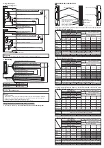
<Using PNP output>
●
I/O circuit diagrams
Main circuit
Main circuit
Emitter
Receiver
6.8kΩ
6.8kΩ
470Ω
(Brown) +V
(Brown) +V
(Pink) Test input
(Pale blue) Output polarity setting / Lockout release input
(Pale blue) Output polarity setting / Lockout release input
(Blue) 0V
(Blue) 0V
Users’ circuit
Users’ circuit
Internal circuit
Internal circuit
*S1
24V DC
+20 -30
%
24V DC
+20 -30
%
+
+
–
–
K1
K2
(Black) Control output 1 (OSSD 1)
(White) Control output 2 (OSSD 2)
0.1µF
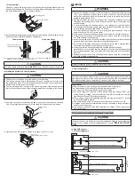
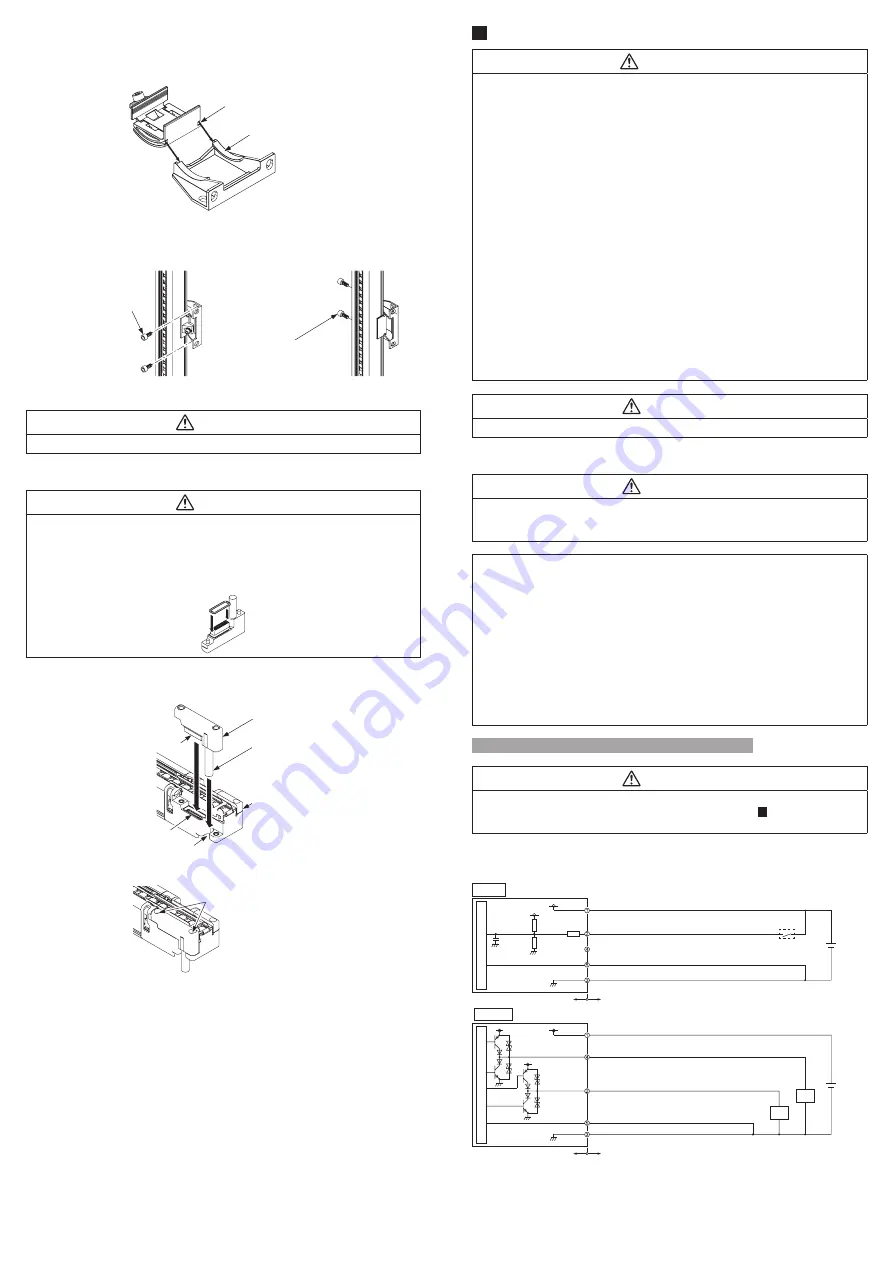
<Side mounting>
Slide and remove the fixing fitting of the intermediate supporting bracket from the
base bracket. Change the direction of the fixing fitting, and engage the notches on
the fixing fitting with the rails on the base bracket.
Notch on fixing fitting
Rail on base bracket
3.
Install the intermediate supporting bracket on the mounting surface with two hexa-
gon-socket head bolts [M5 (purchase separately)].
Hexagon-socket head bolt
[M5 (purchase separately)]
Hexagon-socket head bolt
[M5 (purchase separately)]
<Side mounting>
<Rear mounting>
Note: When the number of beam axes is
SF4D-F□
: 111 or more beam axes,
SF4D-H□
: 56 or more beam axes,
SF4D-A□
: 28 or more beam axes, one set is required.
CAUTION
The intermediate supporting bracket
MS-SFB-2
is not intended to secure the device.
<Installing the bottom cap cables (Option)>
CAUTION
●
Take care not to misplace any screws while you are working.
●
The bottom cap cables are distinguished by round connector color. Gray is for
the emitter, and black is for the receiver. Make sure that the correct cable is con-
nected to the emitter and to the receiver.
●
There is packing on the connector of the bottom cap cable. If the packing is not fit
-
ted on the connector properly, fit as shown below before connecting to the device.
1.
Insert the connector of the bottom cap cable (option) into the connector on the de-
vice. When inserting the connector, fit the cable into the groove on the device.
Groove
Bottom cap cable
(Option)
Cable
This device
Connector
Connector
2.
Tighten the two M2.6 screws. Tighten to a torque of 0.3N·m or less.
M2.6 screw
(Included with bottom cap cable)


