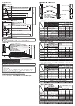
Using line synchronization setting and 8-core cable
<Using PNP output>
●
I/O circuit diagrams
Main circuit
Main circuit
Emitter
Receiver
6.8kΩ
6.8kΩ
0.1µF
0.1µF
6.8kΩ
6.8kΩ
6.8kΩ
0.1µF
6.8kΩ
470Ω
470Ω
470Ω
(Brown) +V
(Brown) +V
(Pink) Test / Reset input
(Orange) Synchroni
(Orange) Synchroni
(Red) Auxiliary output
(Pale purple) Interlock setting input
(Orange / Black) Synchronization -
(Orange / Black) Synchronization -
(Pale blue) Output polarity setting / Lockout release input
(Pale blue) Output polarity setting / Lockout release input
(Blue) 0V
(Blue) 0V
Users’ circuit
Users’ circuit
Internal circuit
Internal circuit
*S1
*S1
K1 K2
24V DC
+20 -30
%
+
‒
K1
Load
K2
(Black) Control output 1 (OSSD 1)
(Pale purple) External device monitor input
(White) Control output 2 (OSSD 2)
<Reference>
K1, K2: External device (forcible guide relay or magnetic contactor)
●
Basic wiring
(Orange) Synchroni
(Orange) Synchroni
(Red) Auxiliary output
(Pale purple) Interlock setting input
(Orange / Black) Synchronization -
(Orange / Black) Synchronization -
(Pale purple) External device monitor input
(Brown) +V
(Brown) +V
(Pink) Test / Reset input
(Pale blue) Output polarity setting / Lockout release input
(Pale blue) Output polarity setting / Lockout release input
(Blue) 0V
(Blue) 0V
24V DC
+20 -30
%
+
-
K1
K2
(Black) Control output 1 (OSSD 1)
(White) Control output 2 (OSSD 2)
Emitter
Receiver
Gray cable
Gray cable
(with black line)
Interlock function
Invalid (auto reset)
External device monitor function
Invalid
Auxiliary output
Cannot be used
<Reference>
K1, K2: Safety relay unit, etc.
*S1
Switch S1
• Test / Reset input
Manual reset …Vs to Vs ‒2.5V (sink current 5mA or less): Emission halt (Note), Open: Emission
Auto reset …Vs to Vs ‒2.5V (sink current 5mA or less): Emission (Note), Open: Emission halt
• Interlock setting input, External device monitor input
Vs to Vs ‒2.5V (sink current 5mA or less): Valid (Note), Open: Invalid
Note: Vs is the supply voltage.
●
Basic wiring
(Brown) +V
(Brown) +V
(Pink) Test input
(Pale blue) Output polarity setting / Lockout release input
(Pale blue) Output polarity setting / Lockout release input
(Blue) 0V
(Blue) 0V
24V DC
+20 -30
%
24V DC
+20 -30
%
+
+
–
–
K1
K2
(Black) Control output 1 (OSSD 1)
(White) Control output 2 (OSSD 2)
Emitter
Receiver
Gray cable
Gray cable (with black line)
*S1
Switch S1
• Test input
Vs to Vs ‒ 2.5V (sink current 5mA or less): Emission halt, Open: Emission (Note)
Note: Vs is the supply voltage.
<Reference>
K1, K2: Safety relay unit, etc.
<Using NPN output>
●
I/O circuit diagrams
0.1µF
Main circuit
Main circuit
Emitter
Receiver
6.8kΩ
6.8kΩ
470Ω
(Brown) +V
(Brown) +V
(Pink) Test input
(Pale blue) Output polarity setting / Lockout release input
(Pale blue) Output polarity setting / Lockout release input
(Blue) 0V
(Blue) 0V
Users’ circuit
Users’ circuit
Internal circuit
Internal circuit
*S1
24V DC
+20 -30
%
24V DC
+20 -30
%
+
+
–
–
K2
K1
(Black) Control output 1 (OSSD 1)
(White) Control output 2 (OSSD 2)
●
Basic wiring
(Brown) +V
(Brown) +V
(Pink) Test input
(Pale blue) Output polarity setting / Lockout release input
(Pale blue) Output polarity setting / Lockout release input
(Blue) 0V
(Blue) 0V
24V DC
+20 -30
%
24V DC
+20 -30
%
+
+
-
-
K1
K2
(Black) Control output 1 (OSSD 1)
(White) Control output 2 (OSSD 2)
Emitter
Receiver
Gray cable
Gray cable (with black line)
*S1
Switch S1
• Test input
0 to +2.5V (source current 5mA or less): Emission halt, Open: Emission
<Reference>
K1, K2: Safety relay unit, etc.


