Adjustment
© Panasonic Industrial Devices SUNX Co., Ltd. 2017
80
2-6-2 Operation Test
Step 1 Supply power to the device.
Step 2 When the device starts, “ ” (when PNP output is set) or “ ” (when NPN output is set)
lights up in yellow on the digital indicator.
Step 3 Make sure that the digital indicators on the emitter and receiver are OFF.
If a yellow number blinks or lights in the digital indicator, refer to
and inform your technician.
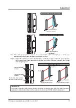
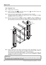
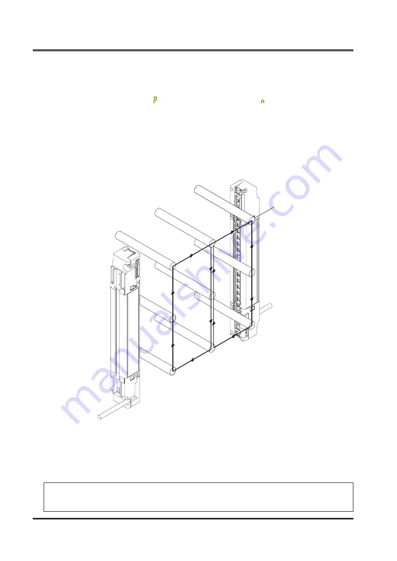
Step 4 Move the test rod (ø14mm for
SF4D-F
□, ø25mm for
SF4D-H
□, ø45mm for
SF4D-A
□) up
and down directly in front of the emitter (A), midway between the emitter and the receiver
(B), and directly in front of the receiver (C) (3 positions) at a speed of 1,600mm/sec. or less.
Test rod
(A)
(B)
(C)
Emitter
Receiver
Step 5 While moving the test rod in Step 4, verify that the control output (OSSD 1 / 2) is OFF
while the test rod is in the sensing area. In addition, verify that the OSSD indicator of
the receiver and the operation indicator of the emitter both light red.
If the operation of the control output (OSSD 1 / 2) and the indicators of the emitter and
receiver do not match the movement of the test rod, refer to
and inform your technician.
<Reference>
If an indicator indicates the light-received state when the test rod blocks light, make sure there are
no reflective objects or scattered light in the vicinity.
Summary of Contents for SF4D-x-01 Series
Page 2: ... Panasonic Industrial Devices SUNX Co Ltd 2017 2 MEMO ...
Page 126: ...Functions Panasonic Industrial Devices SUNX Co Ltd 2017 126 MEMO ...
Page 130: ...Maintenance Panasonic Industrial Devices SUNX Co Ltd 2017 130 MEMO ...
Page 140: ...Troubleshooting Panasonic Industrial Devices SUNX Co Ltd 2017 140 MEMO ...
Page 174: ... Panasonic Industrial Devices SUNX Co Ltd 2017 174 MEMO ...


