9 Self-Diagnosis and Special Mode Setting
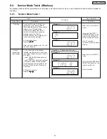
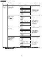
9.1. Wireless Service Mode Summary Table
The service modes can be activated by pressing various button combination on the player and remote control unit.
Below is the summary of major checking:
Player buttons
Remote control unit buttons
Application
Note
FAST FORWARD
3
ID setting
(Refer to the section
“9.2.1. ” for more
information).
SECOND SELECTOR
(press & hold)
Active transmitter display
STOP
(only in AUX)
4
RF channel 1 display
(Refer to the section
“9.2.2. ” for more
information).
5
RF channel 2 display
6
RF channel 3 display
7
Auto RF channel display
Note:
Main room refers to the location of the main unit.
20
SH-FX85P / SH-FX85PC
Summary of Contents for SH-FX85P
Page 12: ...7 4 Digital Receiver Operations as stand alone audio amplifier SB FX85 12 SH FX85P SH FX85PC ...
Page 39: ...11 2 Checking of D Amp and D Port P C B 39 SH FX85P SH FX85PC ...
Page 41: ...12 1 3 PANEL P C B 4GH 0Q 1 2 56 0 5 2 2 2 0 2 2 0 2 3 3 3 3 3 41 SH FX85P SH FX85PC ...
Page 42: ...12 2 Waveform Chart RF TEST POINT PLAY 42 SH FX85P SH FX85PC ...
Page 44: ...SH FX85P SH FX85PC 44 ...
Page 48: ...SH FX85P SH FX85PC 48 ...
Page 50: ...50 SH FX85P SH FX85PC ...
Page 66: ...SH FX85P SH FX85PC 66 ...
Page 70: ...70 SH FX85P SH FX85PC ...
Page 71: ...20 Exploded Views 20 1 Cabinet Parts Location SH FX85P SH FX85PC 71 ...

