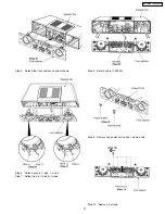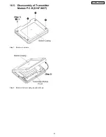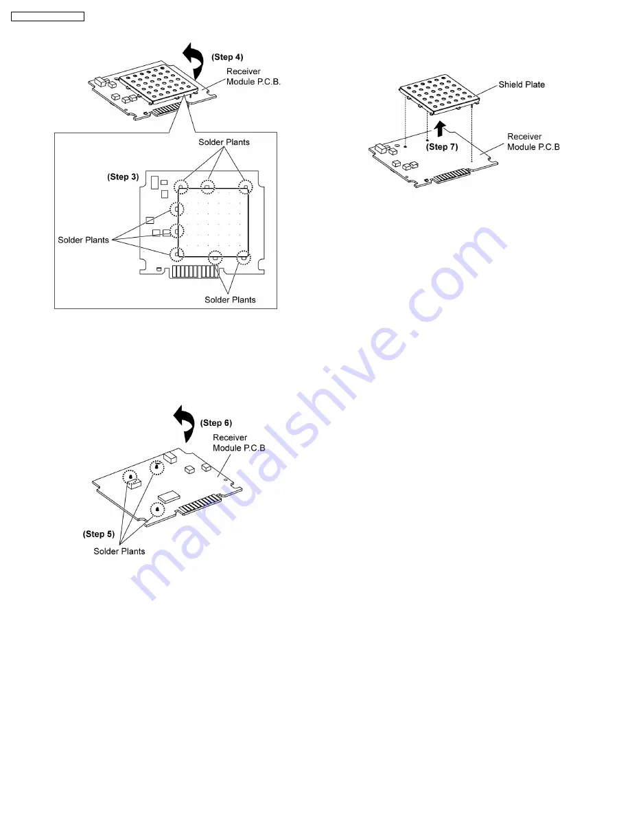
Step 3 : Desolder the 7 soldering locations of shield plate onto
Receiver Module P.C.B..
Step 4 : Flip over the Receiver Module P.C.B..
Step 5 : Desolder the 3 soldering locations of the other side of
Receiver Module P.C.B..
Step 6 : Flip over the Receiver Module P.C.B..
Step 7 : Remove the shield plate as arrow shown.
Cautions :
1. Ensure that the metal plate is facing outwards when
placing back the Receiver module P.C.B..
2. Ensure to fix the shield plate by aligning the locating
pins of shield plate into holes of Receiver Module
P.C.B..
34
SH-FX85P / SH-FX85PC
Summary of Contents for SH-FX85P
Page 12: ...7 4 Digital Receiver Operations as stand alone audio amplifier SB FX85 12 SH FX85P SH FX85PC ...
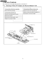
Page 39: ...11 2 Checking of D Amp and D Port P C B 39 SH FX85P SH FX85PC ...
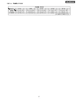
Page 41: ...12 1 3 PANEL P C B 4GH 0Q 1 2 56 0 5 2 2 2 0 2 2 0 2 3 3 3 3 3 41 SH FX85P SH FX85PC ...
Page 42: ...12 2 Waveform Chart RF TEST POINT PLAY 42 SH FX85P SH FX85PC ...
Page 44: ...SH FX85P SH FX85PC 44 ...
Page 48: ...SH FX85P SH FX85PC 48 ...
Page 50: ...50 SH FX85P SH FX85PC ...
Page 66: ...SH FX85P SH FX85PC 66 ...
Page 70: ...70 SH FX85P SH FX85PC ...
Page 71: ...20 Exploded Views 20 1 Cabinet Parts Location SH FX85P SH FX85PC 71 ...


