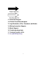
emitted from the pickup lens.
- Avoid exposure to the laser beam, especially when performing
adjustments.
This unit (SJ-HD515) is designed to operate on power supplied
from the Amplifier (SE-HD515MD) through the Tuner (ST-
HD515MD). When connecting the unit to other system components,
do not connect to the Amplifier (SE-HD515MD) directly. When
operating the unit (SJ-HD515) alone for testing and servicing
without having power supplied from the Amplifier (SE-HD515MD),
use the following method.
9.1. Power Supply to This Unit alone
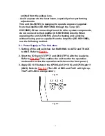
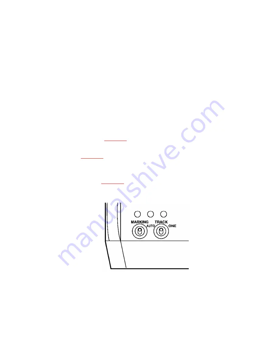
1. Setting of the unit switches: Set MARKING to AUTO and TRACK
to ONE. Refer to
Fig. 9-1.
2. Short the IC10-pin 67 (TP77) and GND (TP74) with the lead wire.
Refer to
Fig. 9-2.
(This enables the unit to enter the operation
mode and to active the operation switches on the front panel.)
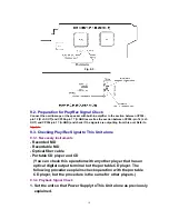
3. Apply DC 10 V between the CP304-pin 5 (+10 V) and CP304-pin 11
(GND). Refer to
Fig. 9-3.
(The LED of REC and PLAY will light up.
The PLAY LED is orange color.)
Fig. 9-1.
Fig. 9-2.
17
Summary of Contents for SJ-HD515
Page 8: ...8 ...
Page 9: ...9 ...
Page 10: ...10 ...
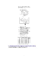
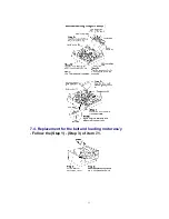
Page 11: ...7 4 Replacement for the belt and loading motor ass y Follow the Step 1 Step 3 of item 7 1 11 ...
Page 12: ...12 ...
Page 14: ...14 ...
Page 46: ...F000306000YM KH 46 ...

