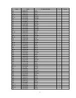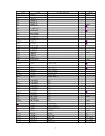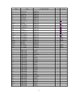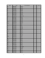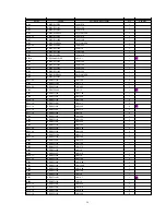
Pin
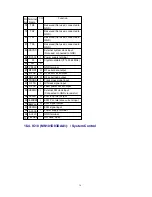
No.
Terminal
Name
I/O
Function
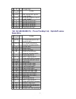
1
DO1
I/O DRAM data 1 input/output
2
DO2
I/O DRAM data 2 input/output
3
WE
I
DRAM write enable input
4
RAS
I
DRAM row address strobe input
5
A9
I
DRAM address 9 input
9
A0
I
DRAM address 0 input
10
|
12
A1
|
A3
I
DRAM address 1 - 3 input
13
V
CC
I
Power supply terminal
14
|
18
A4
|
A8
I
DRAM address 4 - 8 input
22
OE
-
DRAM output enable input
(Not used, connected to GND)
23
CAS
I
DRAM column address strobe
input
24
DO3
I/O DRAM data 3 input/output
25
DO4
I/O DRAM data 4 input/output
26
V
SS
-
GND terminal
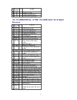
16.6. IC901 (M30218MAA102): / System Control/FL Display
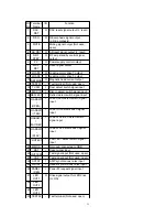
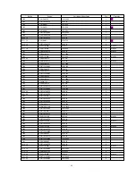
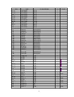
Pin
No.
Terminal
Name
I/O
Function
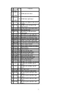
1
P97
-
Not used, connected to GND
2
P96
-
Not used, connected to GND
3
P95
O
Digital in 1 ON signal output
4
P94
O
Digital in 2 ON signal output
5
P93
-
Not used, connected to GND
6
P92
I
Chip select signal input
7
P91
O
Request signal output
8
P90
O
Reset signal output
9
CNV
SS
O
Flash ROM write power supply
10
P87
O
LED drive control signal output
11
P86
-
Not used, connected to GND
12 /RESET
I
Reset signal input (L: Reset)
13
XOUT
O
Crystal oscillator output (f=10 MHz)
14
V
SS
-
GND terminal
15
XIN
I
Crystal oscillator input (f=10 MHz)
16
V
CC
I
Power supply terminal
17
P85
I
AC detect signal input
18
P84
I
Remote control signal input
19
P83
I
Load TRG det. switch signal input
20
P82
O
Audiio mute signal output (H: Mute)
21
P81
O
DA/AD power control signal output
39
Summary of Contents for SJ-MD150
Page 5: ...4 Caution for AC Mains Lead 5 ...
Page 10: ...10 ...
Page 15: ...15 ...
Page 16: ...16 ...
Page 17: ... Check the MD servo P C B B side as shown below 17 ...
Page 19: ...19 ...
Page 20: ...20 ...
Page 21: ...21 ...
Page 22: ...8 7 Replacement for the belt and loading motor Follow the Step 1 Step 3 of item 8 1 22 ...
Page 23: ...23 ...
Page 25: ...25 ...
Page 36: ...30 TEST02 Test terminal Not used open 36 ...
Page 48: ...48 ...
Page 57: ...20 MD Mechanism Unit Parts Location 57 ...
Page 58: ...21 Packaging 58 ...
Page 59: ...F000300000YM KH 59 ...

