NO
YES
NO
YES
YES
NO
YES
NO
YES
3
NO
YES
NO
NO
YES
NO
YES
NO
YES
NO
YES
4
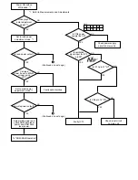
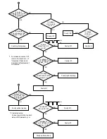
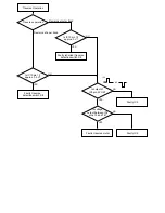
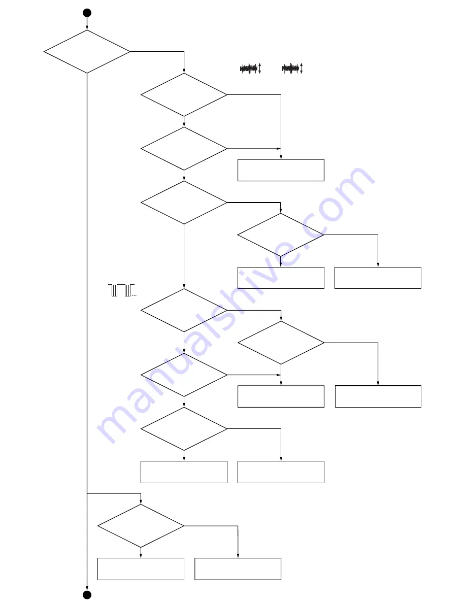
Is TOC read
and disc data
displayed?
Does IC10
pin 13 change from
"H" to "L"?
Faulty IC10
Faulty S4
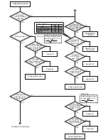
Is there
output from IC1
pins 11 (TP55) and
16 (TP57)? *1
Can
waveform of IC1
pin 11 be adjusted so that
it is approx. symmetrical
with a level of
0.1 Vp-p?
*1
Faulty IC1 or
optical pickup
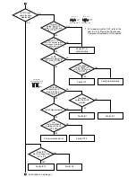
Is RF
waveform output from
IC1 pin 32 (TP52)?
*1
Is there
output from IC1
pin 29 (TP148 or
IC3 pin 87)?
*1
IC1 pin 29
(TP148 or IC3 pin 87)
Is RF signal stable?
Are
communications
between IC3 and
IC72 OK?
Communications error
Is voltage
output from IC3
pin 96?
Faulty IC1
Faulty IC1
Faulty IC3
Faulty IC72
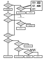
Is voltage
output from IC1
pins 38 (TP44) and
39 (TP37)?
*1
Faulty optical pickup
(Continued on next page.)
For measurements of IC1, refer to the
item 8.5.2. of "Operation Checks and
Component Replacement Procedures".
*1:
2ms. 50mV/DIV.
0.1V
P-P
IC1 pin 11
2ms. 50mV/DIV.
50mV
P-P
IC1 pin 16
0V
3.3V
2ms. 1V/DIV.
Summary of Contents for SJ-MD150
Page 5: ...4 Caution for AC Mains Lead 5 ...
Page 10: ...10 ...
Page 15: ...15 ...
Page 16: ...16 ...
Page 17: ... Check the MD servo P C B B side as shown below 17 ...
Page 19: ...19 ...
Page 20: ...20 ...
Page 21: ...21 ...
Page 22: ...8 7 Replacement for the belt and loading motor Follow the Step 1 Step 3 of item 8 1 22 ...
Page 23: ...23 ...
Page 25: ...25 ...
Page 36: ...30 TEST02 Test terminal Not used open 36 ...
Page 48: ...48 ...
Page 57: ...20 MD Mechanism Unit Parts Location 57 ...
Page 58: ...21 Packaging 58 ...
Page 59: ...F000300000YM KH 59 ...

