Adjustment mode
Display
Laser power adjustment
T0J
Off-set automatic adjustment
T1J
Magneto-optical disc automatic adjustment
T2J
Playback-only disc automatic adjustment
T3J
Jitter meajurement (74minutes)
T4J
Jitter meajurement (60 minutes)
T5J
Destination change
T6J
Off-set automatic adjustment value check
T7J
Magneto-optical disc automatic adjustment
value check
T8J
Playback-only disc automatic adjustment value
check
T9J
Error rate measurement (double velocity)
TAJ
ROM collection
TBJ
DRAM check
TCJ
Aging
TDJ
Tilt measurement
TEJ
PWB inspection
TFJ
*In the display of T0J ~ TFJ shown above, you must adjust T0J , T1J , T2J and
T3J . You must perform the adjustment by observing the order T0J T1J T2J
T3J .
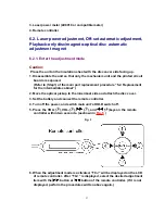
6.2.2. Laser Power Adjustment
Adjust each laser power: read power for reading (play).
6.2.2.1. Set the Unit to the Adjustment Mode
Cautions
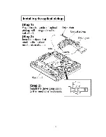
About handling the optical pickup and the magnetic head.
-
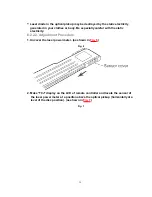
The optical pickup is structured precisely; therefore, it is very fragile. Be
careful not to touch it with the edge of the laser power meter. Do not touch
the lens.
-
The sensor of the laser power meter is a very fine part. Be careful not to touch
it to the optical pickup lens.
-
The focus point of the laser reaches to 356°F. Therefore, avoid adjusting
using laser power for a long time because the sensor of the laser power
meter may be burned.
-
Do not set the unit to the laser power adjustment mode with the MD loaded.
Doing so may result in damage to the MD.
28
Summary of Contents for SJ-MJ50GH
Page 5: ...3 Operating Instructions 4 Handling Precautions for MD Mechanism Optical 5 ...
Page 10: ... Check the P C B as shown below 10 ...
Page 11: ...5 2 Replacement for the disc cover ass y 11 ...
Page 12: ...5 3 Replacement for the side cabinet ass y Follow the Step 1 Step 3 of item 5 1 12 ...
Page 13: ...13 ...
Page 15: ...15 ...
Page 17: ...17 ...
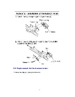
Page 18: ...5 6 Replacement for the traverse motor Follow the Step 1 Step 3 of item 5 1 18 ...
Page 19: ...19 ...
Page 20: ...20 ...
Page 22: ...22 ...
Page 23: ...23 ...
Page 24: ...24 ...
Page 25: ...25 ...
Page 35: ...35 ...
Page 36: ...36 ...
Page 37: ...37 ...
Page 38: ...38 ...
Page 39: ...39 ...
Page 40: ...40 ...
Page 41: ...41 ...
Page 42: ...8 Schematic Diagram Notes 8 1 Type Illustration of IC s Transistors and Diodes 42 ...
Page 53: ...29 CHARGE O Recharge control output terminal 53 ...


