Pin
No.
Mark
I/O /
Division
Function
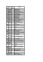
31
CT
O
Triangular wave output
terminal / (connected GND
through capacitor)
32
SPRT
O
Output terminal for setting
of constants anti-power OFF
/ (connected to GND
through capacitor)
33
OFF
—
DC/DC converter OFF(Not
used, open)
34
BOUT
O
Amplifier output terminal
(Not used, open)
35 STROBE
I
Strobe input terminal
36
SEI
I
Sub DC/DC converter error
amplifier input terminal (Not
used, open )
37
VSUB
I
Power supply input terminal
38
SSW
39
SV
CC
40
USW
I
DC/DC converter coil drive
input terminal
16.5. IC501(MN662782RPT1): Servo Processor, Digital Signal
Processor, Digital Filter and D/A Converter
Pin
No.
Mark
I/O /
Division
Function
1
DV
DD
5V
—
Power supply terminal (5V)
2~3
D0~D1
I/O
DRAM data input/output
terminal
4
NWE
O
DRAM write enable output
terminal
5
NRAS
O
DRAM row address strobe
output terminal
6~7
D2~D3
I/O
DRAM data input/output
terminal
8
NCAS1
O
DRAM culmun address
strobe output terminal
9
NCAS2
O
Not used, open
10~14 A8~A4
O
DRAM address output
terminal
15
A9
16~19 A0~A3
20
DV
SS
2
—
GND (digital circuit) terminal
39
Summary of Contents for SL-VP48
Page 8: ...8 ...
Page 9: ... Check the video P C B A side as shown below 5 1 2 Checking for the video P C B B side 9 ...
Page 13: ...13 ...
Page 14: ...14 ...
Page 15: ...5 4 Replacement for the traverse motor Follow the Step 1 Step 5 of item 5 1 1 15 ...
Page 16: ...5 5 Replacement for the optical pickup Follow the Step 1 Step 5 of item 5 1 1 16 ...
Page 17: ... Follow the Step 1 Step 5 of item 5 4 17 ...
Page 28: ...28 ...
Page 29: ...29 ...
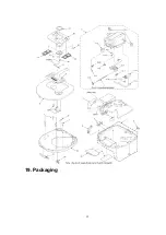
Page 52: ...19 Packaging 52 ...


