8 Disassembly and Assembly Instructions
8.1.
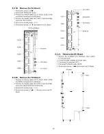
Tuner box
8.1.1.
Remove the Top case
1. See Service Hint (Section 3.1.1.)
8.1.2.
Remove the Rear panel
1. Remove the screws (x4
x4 O , x2 c ^ )
2. Remove the Rear panel.
Rear panel
П - Г ^
L
' u u u u u
I
ooooooo •
I
o o
o o
oo
oo
.
o o
o o
o o o o o o o „
0
ooooo
cS
-- 1
_«c=i
£ s
* ( 4 = | л т О
»a
r^r. ^ Д p- у ^
_ J О О О
8.1.3.
Remove the Q-Board
Caution:
To remove RC.B. w ait 1 minute after power was off for dis
charge from electrolysis capacitors.
1. Disconnect the connector (P1).
2. Disconnect the bridge connector (A10-P9).
3. Remove the screws (x4 ^ ) and remove the Q-Board.
4. Remove the Q-board barrier.
A10-P9
8.1.4.
Remove the Front panel assy
1. Remove the claws (x2
x2 cz|>, x3 >=►) and remove
the Front panel assy.
Tuner box top side
■
I
I.
™ „пцЭ-
Front panel assy
Tuner box back side
Front panel assy
8.1.5.
Remove the K-Board
1. Remove the Front panel assy. (See section 8.1.4.)
2. Remove the screws (x3 ^ ) .
3. Disconnect the connector (K12) and remove the K-Board.
K12
Front panel assy
8.1.6.
Remove the G-Board
1. Remove the Front panel assy. (See section 8.1.4.)
2. Remove the screws (x6
x1 cz|>) and remove the
Front terminal shield.
Front term inal shield
Q-Board barrier
3. Remove the screws (x2 ^ ) and remove the Terminal
rear shield.
4. Disconnect the bridge connectors (A51-G51 and A52-
G52).
27
Summary of Contents for SP-R54Z1
Page 24: ...6 4 No Picture Drive circuits LED indicator f i i D16583 j D16253 SC Board SS Board 24 ...
Page 42: ...42 ...
Page 43: ...10 Block Diagram 10 1 Main Block Diagram Tuner box 43 ...
Page 45: ...10 3 Tuner box 1 3 Block Diagram и FR O N T TERM INAL 45 ...
Page 48: ...10 6 Display unit 1 4 Block Diagram d a d ig it a l s ig n a l p r o c e s s o r 48 ...
Page 50: ...10 8 Display unit 3 4 Block Diagram E POW ER SUPPLY 50 ...
Page 52: ...52 ...
Page 59: ...12 2 Tuner box 12 2 1 G and K Board Schematic Diagram с D E F 1 2 3 4 ...
Page 60: ...5 1 6 1 7 1 8 1 9 58 ...
Page 61: ...12 2 2 А В С D Е F GS Board Schematic Diagram 1 2 3 4 5 6 7 8 9 59 ...
Page 63: ...12 2 4 A Board 2 28 Schematic Diagram Д A BOARD 2 28 TXN A1JXUR TO DH BOARD DH72 10 11 12 13 ...
Page 64: ...т о K BOARD 14 15 16 17 18 61 ...
Page 68: ...еэ 9 se ре ее ге ...
Page 70: ...о 41 42 43 44 45 64 ...
Page 72: ...51 52 53 54 ...
Page 74: ...A D M PX NON USE Adress Data Multi PleX 59 60 61 66 ...
Page 77: ...SS NON USE SS PDP EEPROM EEPROM IC 8502 TVRQ771AA 16K BIT 2K BYTE 78 79 80 81 ...
Page 85: ...131 132 133 134 135 74 ...
Page 87: ...140 141 142 143 144 75 ...
Page 93: ... D D R 2 _ 0 IC5001 C3ABRY000038 185 186 187 188 189 80 ...
Page 96: ...203 204 205 206 207 82 ...
Page 98: ...12 2 27 A Board 25 28 Schematic Diagram 217 218 219 2 2 0 221 2 2 2 223 224 225 84 ...
Page 101: ...SUB3 3V г г 3 IC5300 т г т n I I COCSOBDOOOA gc o s j v I u т T 1 239 240 241 242 243 86 ...
Page 106: ...12 3 Display unit 12 3 1 P SUS Board Schematic Diagram 91 ...
Page 107: ...12 3 2 P MULTI Board 1 2 Schematic Diagram 92 ...
Page 110: ...то Р M U LT I B O A R D AKS02B VTL32 ...
Page 111: ...12 3 5 А В С D Е F PB Board Schematic Diagram 95 ...
Page 112: ...12 3 6 GL KA J S and SG Board Schematic Diagram A В D E KEY SWITCH 1 2 3 4 ...
Page 113: ... S BOARD TNPA4863 га 5W2500 чм ЕЁЭ Ь 1 1 Р в 8 1 Ч 13 ИJ а I f 5 6 7 8 9 96 ...
Page 114: ...12 3 7 А В С D Е F GH Board Schematic Diagram 1 2 3 4 5 6 7 8 9 97 ...
Page 115: ...12 3 8 А В С D Е F DA Board 1 18 Schematic Diagram А DA BOARD 1 18 TZTNP02JW U E IIC г т п 98 ...
Page 122: ...60 61 62 63 ...
Page 124: ...б о о о 00 О О О 68 69 70 71 72 105 ...
Page 125: ...12 3 16 DA Board 9 18 Schematic Diagram 73 74 75 76 77 78 79 80 81 106 ...
Page 126: ...12 3 17 DA Board 10 18 Schematic Diagram IC 25100 MN84527 I sc 82 83 84 85 ...
Page 127: ...86 87 88 89 90 107 ...
Page 129: ...12 3 19 DA Board 12 18 Schematic Diagram 100 101 102 103 104 105 106 107 108 109 ...
Page 130: ...12 3 20 DA Board 13 18 Schematic Diagram 109 110 111 112 113 114 115 116 117 110 ...
Page 131: ...12 3 21 DA Board 14 18 Schematic Diagram 118 119 120 121 122 123 124 125 126 111 ...
Page 136: ...J A 3 PB BOAftD PB6j 9 _ 3 v 9 _ _ Jrovie 9 1 9 ir low Z 5 TO Ы 9 159 160 161 162 ...
Page 137: ...12 3 26 C1 Board 1 2 Schematic Diagram C1 BOARD TNPA4770AC 1 2 В D F 1 2 ...
Page 138: ...мН I i h I I CB2 11 j l j i n I L i Г 116 ...
Page 141: ...12 3 29 C2 Board 2 2 Schematic Diagram 10 11 12 13 14 15 16 17 18 119 ...
Page 142: ...12 3 30 C3 Board 1 2 Schematic Diagram D E A СЗ BOARD TNPA4772AC 1 2 В F 1 9 120 ...
Page 143: ...12 3 31 C3 Board 2 2 Schematic Diagram A СЗ BOARD TNPA4772AC 2 2 10 11 12 13 ...
Page 144: ...14 15 16 17 18 121 ...
Page 150: ...12 3 37 SS Board 2 2 and SS2 Board Schematic Diagram 10 11 12 13 14 15 16 17 18 127 ...
Page 154: ...A BOARD COMPONENT SIDE TXN A1JXUR 130 ...
Page 166: ...P MULTI BOARD COMPONENT SIDE ETX2MM718EBS A I В I С I D I Ё 138 ...
Page 171: ...13 2 6 DA Board ...
Page 173: ...DA BOARD COMPONENT SIDE TZTNP02JWUE A I В I С I D I E I F I G I H I I 144 ...
Page 184: ...SS2 B0ARD COMPONENT SIDE TNPA4843 H 153 ...
Page 185: ...154 ...
Page 187: ...14 1 2 Exploded View 2 Display unit 1 156 ...
Page 188: ... 5 14 1 3 Exploded View 3 Display unit 2 157 ...
Page 189: ...14 1 4 Packing 1 158 ...
Page 190: ...14 1 5 Packing 2 TUNER BOX 159 ...
Page 191: ...14 1 6 Packing 3 160 ...
Page 192: ...14 1 7 Packing 4 Pedestal ...
Page 193: ...14 1 8 Packing 5 162 ...
Page 194: ...14 1 9 Packing 6 DISPLAY UNIT 163 ...
Page 195: ...14 1 10 Packing 7 164 ...

