background image

16

6.2.

Packing View

Summary of Contents for SR-JP185WVA-US

Page 1: ...O PMMA150931CE Electric Rice Cooker Model No SR JP185WVA US SR JP185SWVA US SR JP185WVA CA SR JP185SWVA CA SR JP185SBSR ID SR JP185WSR ID SR JP185TSH SG SR JP185WSH SG SR JP185WSW SG SR JP185WSW MN SR JP185SSK MY SR JP185TSK MY SR JP185WSK MY Destination USA Canada Indonesia Singapore DBD Singapore RBD Mongolia Malaysia ...

Page 2: ...ng 8 4 2 Bubble test 8 4 3 Steaming Test 8 4 4 Keep Warm Test 8 5 Disassembly and Assembly Instructions 9 5 1 Replacing the switch assembly 9 5 2 Replacing the outer lid 11 5 3 Replacing the body assembly 12 5 4 Replacing the heating plate 12 5 5 Replacing the temperature limiter 13 5 6 Replacing the thermal fuse 14 6 Exploded View and Replacement Parts List 15 6 1 Exploded View 15 6 2 Packing Vie...

Page 3: ...8 W Porridge 650 W Porridge Indonesia 105 W Cooking Capacity 0 54L 1 8L 3 10 cups Center Thermostat Working Temperature 141 C 5 C Menu Select Quick Cook White Rice Steam Porridge Keep Warm Temperature 65 C 78 C Porridge Cooking Volume 0 54L 1 8L 3 10 cups Power Cord Length 1m Thermal Fuse Specification 250V 15A 142 C Thermal Fuse Quantity 2 Dimension Height 0 287m Weight 0 275m Length 0 270m Produ...

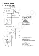
Page 4: ...4 2 Schematic Diagram 2 1 For 120V 650W model 2 2 For 220V 400W model ...

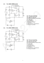
Page 5: ...5 2 3 For 220V 650W model 2 4 For 230V 650W model ...

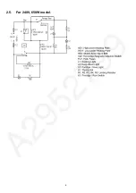
Page 6: ...6 2 5 For 240V 650W model ...

Page 7: ... malfunctions phenomena and if necessary you should also check the inner pot and spill proof moisturizing cap Power off first before checking the related components Check the main unit according to the troubleshooting table below 3 1 Troubleshooting Table Note Mark O means the components that may malfunction ...

Page 8: ...inner pan and or the pan sensor 4 4 Keep Warm Test 1 Place a mercury thermometer between urethane foam blocks Urethane foam blocks ASN 300 and the thermometer ASN 150H are supplied as spare parts 2 Place the urethane foam blocks holding the thermometer in the center of the bottom of the pan and allow the cooker to run in the Keep Warm process 3 More than one hour later open the lid and read the te...

Page 9: ...wise the screwdriver contacted parts will be damaged You must use the above method Upon pulling out connectors and similar things just directly pull them outwards Pulling them out in different directions will impose pressure on the components connected to them to cause damages to the components Upon pulling out the fastening terminals at the chuck please press them down in the direction of the arr...

Page 10: ... to remove the bracket 4 Remove the switch assembly Remove the fixing screws of the control baseplate Push the control baseplate upward along the body assembly to remove the switch assembly 5 Assembly the switch assembly Conduct assembly after control switch assembly replacement as per the disassembly steps in a reversed way Note For wiring refer to Schematic Diagram on P 4 ...

Page 11: ...nge cover Remove the hinge cover using a screwdriver as shown in the dia gram 3 Remove the outer lid Take out the fixed pin for fixing the outer lid 2 pieces Gently take out the outer lid Push the bracket towards the temperature limiter to remove the bracket 4 About assembly Conduct assembly after outer lid replacement as per the disassembly steps in a reversed way ...

Page 12: ...ake out the Body Assembly 1 Remove the base Disassemble the base by referring to Step 1 as shown in 5 1 2 Remove the heating plate Disassemble the connection to the heating plate Remove the fixing screws from the heating plate Remove the heating plate from the protective frame 3 About assembly Conduct assembly after heating plate replacement as per the disassembly steps in a reversed way Note For ...

Page 13: ...witch assembly Separate the Temperature limiter from the connecting rod slot 3 Remove the Temperature limiter Straighten the claws 3 as shown in the diagram right and take out the temperature limiter Note Do not deform the supporting spring when disassembly 4 About assembly Conduct assembly after temperature limiter replacement as per the disassembly steps in a reversed way Note Do not scratch the...

Page 14: ...ing plate 3 Remove the temperature fuse holder and take out the thermal fuse Remove the fixing screws from the theral fuse holder peel off the aluminum foil tape and remove the holder and the thermal fuse Directly take out the thermal fuse 4 Reassembly Conduct assembly after thermal fuse replacement as per the disassembly steps in a reversed way Note Do not make temperature fuse deformed when asse...

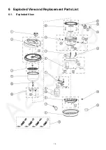
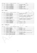
Page 15: ...15 6 Exploded View and Replacement Parts List 6 1 Exploded View ...

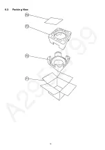
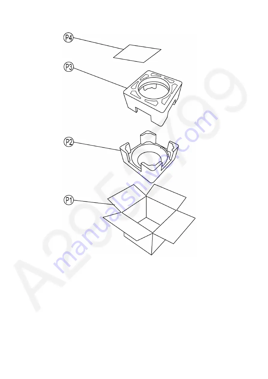
Page 16: ...16 6 2 Packing View ...

Page 17: ...WVA SR JP185WVA 9 2300131479 BODY ASSY 1 SR JP185WSH SR JP185WSK SR JP185WSW 9 2300131483 BODY ASSY 1 SR JP185SSK 9 2300131488 BODY ASSY 1 SR JP185SBSR 9 2300131489 BODY ASSY 1 SR JP185WSR 9 2300131490 BODY ASSY 1 SR JP185TSH SR JP185TSK 9 2300131500 BODY ASSY 1 SR JP185SWVA 9 2300131501 BODY ASSY 1 SR JP185WVA 10 2300150315 PROTECTING FRAME ASSY 1 SR JP185SBSR SR JP185WSR 10 2300150316 PROTECTING...

Page 18: ...0000299 SCREW ST4X14FT 1 H 2100030048 WASHER 4 1 SR JP185SBSR SR JP185WSR SR JP185TSH SR JP185WSH SR JP185WSW SR JP185SSK SR JP185TSK SR JP185WSK I 2100070046 SCREW SET XTN4X8FFJ 2 J 2100000391 SCREW M4X30 1 K 2100000393 SCREW XTN4X5FFJ 2 K 2100000393 SCREW XTN4X5FFJ 4 SR JP185WSR SR JP185SWVA L 2100030009 SPRING WASHER 4 2 L 2100030009 SPRING WASHER 4 SR JP185WSR SR JP185SWVA Safety Ref No Part N...

Reviews: