8.1.16. Ionizer Operation
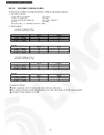
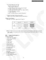
4. When the switch is pressed between 11 to 16 seconds and together with the signal from remote control, the unit can be
changed to different controlling setting (A-B mode) or to testify oxygen operation.
5. When the switch is pressed between 16 to 21 seconds, either “H14” error detection selection mode or the remote control signal
receiving sound can be cancelled or turned on.
8.1.15. Indoor Power Relay Control
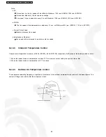
Power relay will turn on during operation or in progress of stopping operation. Although operation stops, the power relay continues
on for three minutes.
However, during an instantaneous power failure (< 0.5s), power relay will turn off. Then, it will turn on 2 minutes after power recover
and the unit will operate as previous operation condition.
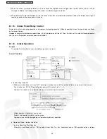
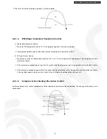
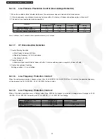
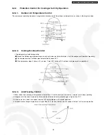
Purpose
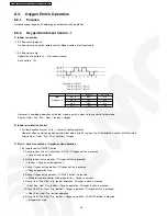
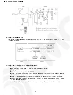
To provide fresh air effect to users by discharging minus ion to air.
Control Condition
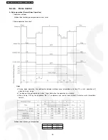
a. Ionizer Only Operation.
1. When an air-conditioner unit is at “OFF” condition (standby) and an ION operation button at remote control is pressed.
Fan & ionizer on, ION LED illuminates, but power LED maintain off. (1
→
2)
However, fan speed can be adjusted later by customer during this operation.
Airflow direction (Horizontal Vane) control:
Follow vane direction control at cooling mode.
Horizontal vane can be changed by customer during ion only operation.
b. Operation Mode + Ionizer Operation.
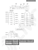
1. Ionising Operation Start Condition
When an air conditioner unit is in “ON” condition (Heat, Cool, Dry, Fan, Auto mode) and an ION operation button at remote
28
CS-XE9DKE CU-XE9DKE / CS-XE12DKE CU-XE12DKE
Summary of Contents for SUPER DELUXE CS-XE9DKE
Page 10: ...4 Dimensions 10 CS XE9DKE CU XE9DKE CS XE12DKE CU XE12DKE...
Page 11: ...11 CS XE9DKE CU XE9DKE CS XE12DKE CU XE12DKE...
Page 12: ...5 Refrigeration Cycle Diagram 12 CS XE9DKE CU XE9DKE CS XE12DKE CU XE12DKE...
Page 13: ...6 Block Diagram 13 CS XE9DKE CU XE9DKE CS XE12DKE CU XE12DKE...
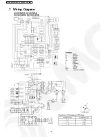
Page 14: ...7 Wiring Diagram 14 CS XE9DKE CU XE9DKE CS XE12DKE CU XE12DKE...
Page 89: ...13 Technical Data 89 CS XE9DKE CU XE9DKE CS XE12DKE CU XE12DKE...
Page 90: ...90 CS XE9DKE CU XE9DKE CS XE12DKE CU XE12DKE...
Page 102: ...102 CS XE9DKE CU XE9DKE CS XE12DKE CU XE12DKE...
Page 103: ...How to use electronic circuit diagram 103 CS XE9DKE CU XE9DKE CS XE12DKE CU XE12DKE...
Page 104: ...18 1 Remote Control 104 CS XE9DKE CU XE9DKE CS XE12DKE CU XE12DKE...

