3. Explaination of operation
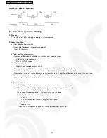
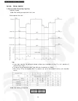
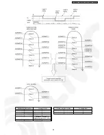
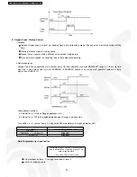
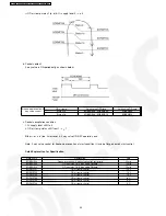
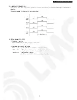
1) Before the deice is started, compressor frequency is set to the specified value for T1-timer.
2) After deice is started, the 4-way valve, OD Fan and ID fan are OFF.
3) After 4-way valve is OFF for 30 s, compressor frequency is set to the specified value.
4) Before deice is ended, if the outdoor heat exchanger temperature exceeds a°C, set compressor frequency and expansion valve to the
specified values.
5) When outdoor heat exchanger temperature exceeds b°C, or 10 minutes has passed since the 4-way valve is OFF, operation at timer T5
will be started.
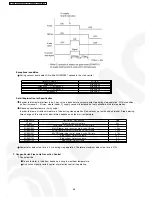
6) After the above 5) operation, if the outdoor heat exchanger temperature exceeds C°C, or after timer T5, the deice operation ending signal
will be produced. The comp. Hz is set to the specified value and at the same time outdoor fan motor ON signal is produced.
7) After T6 the deice ending signal is produced, 4-way valve is set to ON, indoor fan is ON, Compressor frequency is FREE, and return to
normal heating operation.
4. Deice operation judgement condition
When any of below a, b, c, d condition is satisfied, deice signal is produced.
a. Continuously, outdoor heat exchanger temperature < 3°C for 120 minutes and outdoor heat exchanger temperature <
-6°C for 3 minutes and outdoor air temperature > -1°C and Comp. is ON.
b. Continuously, outdoor heat exchanger temperature < 3°C for 80 minutes and outdoor heat exchanger temperature < -
7°C for 3 minutes and outdoor air temperature > -1°C and Comp. is ON.
c.
Continuously, outdoor heat exchanger temperature < 3°C for 40 minutes and outdoor heat exchanger temperature < -
9°C and outdoor air temperature > -3°C for 3 minutes and Comp. is ON.
d. Continuously, outdoor heat exchanger temperature < 3°C for 40 minutes and outdoor heat exchanger temperature < -
11°C for 3 minutes and outdoor air temperature < -3°C and Comp. is ON.
However, the first deice will start only after minimum of 60 minutes in operation.
(2nd deice and onward shall follow above conditions)
39
CS-XE9DKE CU-XE9DKE / CS-XE12DKE CU-XE12DKE
Summary of Contents for SUPER DELUXE CS-XE9DKE
Page 10: ...4 Dimensions 10 CS XE9DKE CU XE9DKE CS XE12DKE CU XE12DKE...
Page 11: ...11 CS XE9DKE CU XE9DKE CS XE12DKE CU XE12DKE...
Page 12: ...5 Refrigeration Cycle Diagram 12 CS XE9DKE CU XE9DKE CS XE12DKE CU XE12DKE...
Page 13: ...6 Block Diagram 13 CS XE9DKE CU XE9DKE CS XE12DKE CU XE12DKE...
Page 14: ...7 Wiring Diagram 14 CS XE9DKE CU XE9DKE CS XE12DKE CU XE12DKE...
Page 89: ...13 Technical Data 89 CS XE9DKE CU XE9DKE CS XE12DKE CU XE12DKE...
Page 90: ...90 CS XE9DKE CU XE9DKE CS XE12DKE CU XE12DKE...
Page 102: ...102 CS XE9DKE CU XE9DKE CS XE12DKE CU XE12DKE...
Page 103: ...How to use electronic circuit diagram 103 CS XE9DKE CU XE9DKE CS XE12DKE CU XE12DKE...
Page 104: ...18 1 Remote Control 104 CS XE9DKE CU XE9DKE CS XE12DKE CU XE12DKE...


