Note:
The illustrations in this manual are for explanation purposes only and may differ from the
actual unit. It is subjected to change without notice for future improvement.
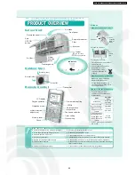
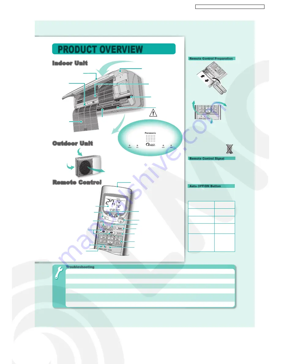
PRODUCT OVERVIEW
Air inlet
(rear)
Air outlet
■
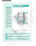
About
Remote Control Preparation
• Make sure it is not obstructed.
• Maximum distances: 10m.
• Certain fluorescent lights may
interfere with signal transmission.
Consult your dealer.
Remote Control Signal
Auto OFF/ON Button
1. Pull out
2. Insert
batteries
(AAA or
R03)
5. Press again to confi rm
• Timer operation will be based on
current time set.
• The batteries can be used for
approximately 1 year.
• The batteries must be
recycled or disposed of
properly.
3. Press CLOCK button
4. Set
current
time
Air inlet
(side)
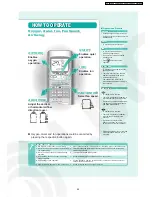
LCD display
Off/On
Fan speed selection
Memory reset
Clock setting
Temperature setting
Ion operation
Operation mode
Quiet operation
Timer setting
Oxygen operation
Airflow direction
adjustment
Remote Control
Remote Control
Transmitter
Check
Troubleshooting
●
Operation delayed for few minutes after restart.
➤
This is a normal self protection control.
●
Sound like water fl owing during operation.
➤
Caused by refrigerant fl ow inside.
●
Mist emerges from indoor unit.
➤
Condensation effect due to cooling process.
●
Noisy during operations.
➤
Installation work could be slanted or front panel didn’t close properly.
●
Remote control/display does not work.
➤
Check whether batteries are correctly inserted or needs replacement.
●
The unit cannot operate.
➤
Check either circuit breaker is tripped, power plug is inserted correctly or
timer is used correctly.
●
Outdoor unit emits water/steam.
➤
Condensation or evaporation happens at piping surface.
• To operate the unit if the
remote control is misplaced or
malfunctioning.
Action
Operation
mode
Press once
Automatic
Operation
Press until “beep”
sound and release.
Cooling
Operation
Press until “beep-
beep” sound and
release.
Heating
Operation
Press until 3“beep”
sound and release.
Press again until
“beep” sound and
release.
Oxygen
Operation
• To OFF, press again the Auto OFF/
ON button.
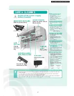
Air intake
Airflow
direction
louver
Air filter
Front panel
I
Indoor Unit
ndoor Unit
Auto
OFF/ON
button
Receiver
Discharged air
Indicators
Ionizer
Do not touch
during operation
Super alleru-buster
Filter
Decorative panel
Outdoor
Outdoor Unit
Unit
53
CS-XE9DKE CU-XE9DKE / CS-XE12DKE CU-XE12DKE
Summary of Contents for SUPER DELUXE CS-XE9DKE
Page 10: ...4 Dimensions 10 CS XE9DKE CU XE9DKE CS XE12DKE CU XE12DKE...
Page 11: ...11 CS XE9DKE CU XE9DKE CS XE12DKE CU XE12DKE...
Page 12: ...5 Refrigeration Cycle Diagram 12 CS XE9DKE CU XE9DKE CS XE12DKE CU XE12DKE...
Page 13: ...6 Block Diagram 13 CS XE9DKE CU XE9DKE CS XE12DKE CU XE12DKE...
Page 14: ...7 Wiring Diagram 14 CS XE9DKE CU XE9DKE CS XE12DKE CU XE12DKE...
Page 89: ...13 Technical Data 89 CS XE9DKE CU XE9DKE CS XE12DKE CU XE12DKE...
Page 90: ...90 CS XE9DKE CU XE9DKE CS XE12DKE CU XE12DKE...
Page 102: ...102 CS XE9DKE CU XE9DKE CS XE12DKE CU XE12DKE...
Page 103: ...How to use electronic circuit diagram 103 CS XE9DKE CU XE9DKE CS XE12DKE CU XE12DKE...
Page 104: ...18 1 Remote Control 104 CS XE9DKE CU XE9DKE CS XE12DKE CU XE12DKE...


