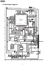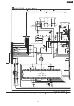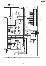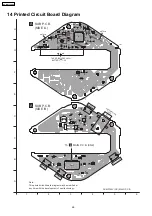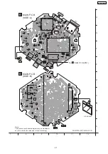
12 Schematic Diagram Notes
Notes:
·
Circuit voltage and waveform described herein shall be
regarded as reference information when probing defect
point, because it may differ from an actual measuring
value due to difference of Measuring instrument and its
measuring condition and product itself.
This schematic diagram may be modified at any time
with the development of new technology.
S1:
PLAY / STOP switch
S2:
FF switch
S3:
REW switch
S4:
Volume up switch (VOL +)
S5:
Volume down switch (VOL -)
S6:
REC switch
S7:
MODE switch
S8:
HOLD switch (HOLD)
·
The supply part number is described alone in the
replacement parts list.
·
Voltage from negative terminal of battery.
( )...MP3 position, [ ]...FM position.
No mark...MP3 AND FM position.
·
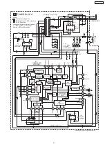
Voltage and signal line
: Positive voltage line
: FM RF signal line
: Audio signal line
: Mp3 signal line
: REC signal line
·
Important safety notice:
Components
identified
by
mark
have
special
characteristic s important for safety.
Furthermore, special parts which have purposes of fire-
retardant (resistors), high-quality sound (capacitors), low-
noise (resistors), etc. are used.
When replacing any of components, be sure to use only
manufacturers specified parts shown in the parts list.
·
Caution!
IC and LSI are sensitive to static electricity.
Secondary trouble can be prevented by taking care during
repair.
Cover the parts boxes made of plastics with aluminum foil.
Ground the soldering iron.
Put a conductive mat on the work table.
Do not touch the legs of IC or LSI with the fingers directly.
21
SV-MP100VGC
Summary of Contents for SV-MP100VGC
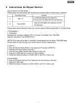
Page 7: ...4 Instructions for Repair Service 7 SV MP100VGC ...
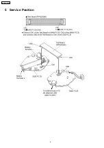
Page 8: ...5 Service Position 8 SV MP100VGC ...
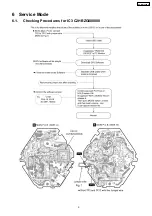
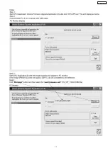
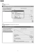
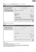
Page 9: ...6 Service Mode 6 1 Checking Procedures for IC3 C2HBZG000008 9 SV MP100VGC ...
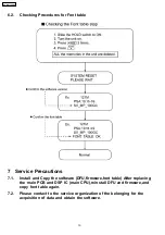
Page 11: ...11 SV MP100VGC ...
Page 12: ...12 SV MP100VGC ...
Page 13: ...13 SV MP100VGC ...

