background image


17 


Fig. 2-2 Mounting to Wall 

Summary of Contents for Switch-M12PWR

Page 1: ... and proper operations of this Switching Hub Please read the Important Safety Instructions on pages 2 to 4 Any problems or damage resulting from disassembly of this Switching Hub by customers are not covered by the warranty Switch M12PWR Model Number PN23129A Operation Manual For Menu Screens ...

Page 2: ...r modify this Switching Hub Deviation could lead to fire electric shock and or equipment failure Do not damage the power cord Do not bend too tightly stretch twist bundle with other cord pinch put under a heavy object and or heat it Damaged the cord could lead to fire short and or electric shock Do not put foreign objects such as metal and combustible into the opening such as twisted pair port con...

Page 3: ...e Do not put this Switching Hub into fire Deviation could lead to explosion and or fire Do not use the supplied power cord for anything other than this product WARNIN WARNIN Use the bundled power cord AC 100 240V specifications Deviation could lead to electric shock malfunction and or equipment failure Unplug the power cord in case of equipment failure Deviation such as keeping connected for a lon...

Page 4: ...rt of this Switching Hub a lightning surge current voltage may be conducted to this Switching Hub through the twisted pair cable leading to malfunction If you connect such a device it is strongly recommended that you install a surge protective device SPD on the twisted pair port side of this Switching Hub A lightning surge current voltage may be conducted to this Switching Hub through the power su...

Page 5: ...a console cable to the console port discharge static electricity for example by touching metal appliance do not discharge by touching this Switching Hub Do not store and or use this Switching Hub in the environment with the characteristics listed below Store and or use this Switching Hub in the environment in accordance with the specification High humidity Possible spilled liquid water Dusty Possi...

Page 6: ...6 malfunction When stacking Switching Hubs leave a minimum of 20 mm space between them is required ...

Page 7: ...tions which may or may not be caused by failure and or malfunction of this device 2 The contents described in this document may be changed without prior notice 3 For any question please contact the retailer where you purchased the product Brands and product names in this document are trademarks or registered trademarks of their respective holders ...

Page 8: ...ting to Wall 16 2 3 Mounting to Steel Product 18 3 Connection 19 3 1 Connecting a Twisted Pair Port 19 3 2 Connecting an SFP Extension Port 21 3 3 Connecting to Power 22 4 Configuration 23 4 1 Connecting via Console Port 23 4 2 Login 24 4 3 Basic Operations on the Screen 27 4 4 Main Menu 29 4 5 General Information Menu 31 4 6 Basic Switch Configuration 33 4 6 1 System Administration Configuration ...

Page 9: ...ying all MAC addresses 70 4 6 8 e Displaying MAC address table by VLAN 71 4 6 9 Time Configuration 73 4 6 10 ARP Table Configuration 75 4 7 Advanced Switch Configuration 77 4 7 1 VLAN Management 79 4 7 1 a Special Features 79 4 7 1 b VLAN Management Menu 80 4 7 1 c VLAN Creation Menu 84 4 7 1 d VLAN Modification Menu 86 4 7 1 e VLAN Port Configuration Menu 88 4 7 2 Link Aggregation 90 4 7 2 a Abou...

Page 10: ... Menu 147 4 7 5 k Create Policy Configuration Menu 149 4 7 6 Quality of Service Configuration 151 4 7 6 a Traffic Class Configuration 152 4 7 6 b Configuration of Scheduling Method 153 4 7 7 Egress Rate Limiting Configuration Menu 154 4 7 8 Storm Control Configuration Menu 155 4 7 9 802 1x Access Control Configuration 158 4 7 9 a IEEE 802 1X Port Based Access Control Configuration 159 4 7 9 b MAC ...

Page 11: ...guration File Upload Download 213 4 9 3 System Reboot 215 4 9 4 Exception Handler 217 4 9 5 Ping Execution 218 4 9 6 System Log 221 4 7 6 a Enable Disable Individual System Log Menu 224 4 9 7 Watch Dog Timer Menu 226 4 10 Save Configuration to Flash 227 4 11 Command Line Interface CLI 228 4 12 Logout 229 Appendix A Specifications 230 Appendix B Procedures for Console Port Configuration using Windo...

Page 12: ...ss cable auto sensing function Simply connect devices with straight cables whether it is a terminal or a network device This function does not work if the port communication configuration is set at Fixed or Link Aggregation Ports 1 to 12 are set at MDI X default SSH Telnet allows remote configuration changes and verifications of the Switching Hub Remotely configure the PoE settings for each port P...

Page 13: ...llation Guide 1 CD ROM PDF version of Operating Instuctions 1 Mounting bracket for 19 inch rack 2 Mounting bracket for wall mount 2 Screws for 19 inch rack 4 Screws for wall mount 4 Screws for fixing the main unit and the mounting bracket 8 Screws for magnetic mount 4 Magnet 4 Rubber foot 4 Power cord CEE7 7 1 The attached power cord iss dedicated for AC 100 240V use ...

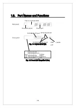
Page 14: ... an nd d F Fu un nc ct ti io on ns s Fig 1 1 Switch M12PWR Fig 1 2 Front LED Magnified View Power port RJ45 console port Back panel Front panel 10 100 1000BASE T port 10 100BASE TX port SFP extension slot Power cord hook block Ground terminal ...

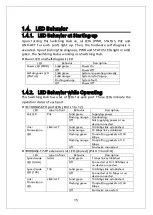
Page 15: ...set of LEDs for each port These LEDs indicate the operation status of each port 10 100BASE TX port LEDs Ports 1 to 12 LED Label in front Behavior Description PoE LED PoE Solid green Supplying power Flashing orange Overloading Off Not supplying power or no device connected Link Transmission LED LINK ACT Solid green 100 Mbps link established Solid orange 10 Mbps link established Flashing green Trans...

Page 16: ...es Fix the mounting brackets and the main unit by tightening four screws each Then by using four screws for 19 inch rack included in this Switching Hub or procured for the lack firmly mount the main unit in the rack Fig 2 1 Mounting to 19 inch Rack 2 2 2 2 M Mo ou un nt ti in ng g t to o W Wa al ll l Take out the supplied two mounting brackets for wall mount and eight screws for fixing the main un...

Page 17: ...17 Fig 2 2 Mounting to Wall ...

Page 18: ...ber feet to dents located at the corners of the bottom face and fix the magnets firmly with the supplied four screws for magnet mount Fig 2 3 Bottom Face Note Do not install the switch in such places as the unstable location where there is strong vibration or shock or where a person may walk under this Switching Hub Deviation could lead to injury or equipment failure Rubber foot Rubber foot ...

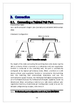
Page 19: ... the port is automatically configured at the highest performance mode When a terminal or a LAN device without auto negotiation function is connected to this Switching Hub this Switching Hub automatically determines and sets the communication speed however the full duplex half duplex configuration is set at half duplex because the full duplex half duplex capability cannot be determined When connect...

Page 20: ...20 function does not work Therefore use a cross cable to connect them ...

Page 21: ...tion The SFP extension port shares the port with the twisted pair port The twisted pair port is enabled however the SFP extension port is automatically enabled when a fiber optical link is established Connect this Switching Hub s TX port to the RX port of the connected device and this Switching Hub s RX port to the TX port of the connected device 1000BASE SX 500 m or shorter 1000BASE LX 10 km or s...

Page 22: ...is Switching Hub and connect the other end into an electric outlet This Switching Hub operates at AC 100 to 240 V 50 60 Hz This Switching Hub does not have a power ON OFF switch Plugging the power cord turns on this Switching Hub s power and it starts operating To power off unplug the power cord from the electric outlet ...

Page 23: ...iguring an IP address refer to 4 6 2 4 4 1 1 C Co on nn ne ec ct ti in ng g v vi ia a C Co on ns so ol le e P Po or rt t Console connection requires a DEC VT100 compatible asynchronous terminal or a terminal capable of running a VT100 compatible terminal emulator such as HyperTerminal on Windows XP or older Connect a terminal of this kind to the RJ45 console port of this Switching Hub Configure th...

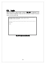
Page 24: ... Fig 4 2 1 is displayed If no similar window is displayed make sure the transmission mode of console is correct or hit the enter key Fig 4 2 1 Login screen Console PN23129K PN23129A Local Management System Version 2 0 0 xx MAC Address 00 C0 8F xx xx xx Login Menu Login ...

Page 25: ...g Hub via Telnet the screen displays Remote Management System on the top similar to Fig 4 2 2 Fig 4 2 2 Login screen Telnet PN23129K PN23129A Remote Management System Version 2 0 0 xx MAC Address 00 C0 8F xx xx xx Login Menu Login ...

Page 26: ...ing Hub s default password is the same as the login name manager Enter the password correctly and press the Return key Fig 4 2 3 Entering password Both the login name and password can be changed For the detailed change procedure refer to 4 6 6 Note Up to four users can access the Switching Hub concurrently via Telnet PN23129K PN23129A Local Management System Version 2 0 0 xx MAC Address 00 C0 8F x...

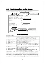
Page 27: ...ting what you need to enter next Follow this instruction 7 Command entry line Enter a command or settings 8 Explanation Displays the explanation and or status of this screen Also displays an entry error message if applicable All operations on this screen are done by entering letters Using a cursor or other operations are not available Available commands letters differ on each screen They are shown...

Page 28: ...28 command If you enter a command or setting not available an error message is shown in the explanation field ...

Page 29: ...dvanced Switch Configuration Configures this Switching Hub s advanced functions such as VLAN link aggregation spanning tree ACL QoS IEEE802 1X authentication IGMP snooping and PoE Statistics Displays this Switching Hub s statistical information Switch Tools Configuration Set this Switching Hub s additional tools such as firmware update saving reading settings Ping and system log Save Configuration...

Page 30: ...30 ...

Page 31: ...formation System up for 000day s 00hr s 00min s 00sec s Boot Runtime Code Version 1 0 0 xx 2 0 0 xx Hardware Information Version Version1 CPU Utilization 0 00 DRAM Flash Size 64MB 8MB DRAM User Area Size Free xxxxxxxx bytes Total xxxxxxxx bytes System Fan Status Good System Temperature CPU xx System xx degree s Celsius Administration Information Switch Name Switch Location Switch Contact System Ad...

Page 32: ...ame The factory default setting is blank For configuration details refer to 4 6 1 Switch Location Displays the Switching Hub s location The factory default setting is blank For configuration details refer to 4 6 1 Switch Contact Displays the contact information The factory default setting is blank For configuration details refer to 4 6 1 System Address Information Items shown here are configured i...

Page 33: ...d port settings such as port name System Security Configuration Configures the security settings such as access limitation for this Switching Hub Mail Report Configuration Configures the E mail report transmission settings Forwarding Database Displays the MAC address table Time Configuration Configures the time settings such as the SNTP based time synchronization function and manual mode settings ...

Page 34: ...rmation The factory default setting is blank Available commands are listed below N Set edit the system name Press N The command prompt changes to Enter system name Enter a Switching Hub name in 50 characters or less L Set edit the device installation location information Press L The command prompt changes to Enter system location Enter a Switching Hub location in 50 characters or less C Set edit t...

Page 35: ...ys the IP address of the router set as a current default gateway 0 0 0 0 is factory default setting DHCP Mode Displays the DHCP mode If enabled the Switching Hub requests an IP address to the DHCP server Disabled is the factory default setting Enabled Requests an IP address from the DHCP server when starting up Disabled Does not request an IP address from the DHCP server when starting up DHCP Rene...

Page 36: ...36 ...

Page 37: ...witching Hub Then the command prompt changes to Enter subnet mask Enter the subnet mask Then the command prompt changes to Enter new gateway IP address Enter the IP address of a router used as a default gateway D Disable enable the DHCP mode If enabled an IP address is automatically obtained from the DHCP server E Enable the DHCP mode A DHCP server must be operating on the network D Disable the DH...

Page 38: ...ap sending settings Quit to previous menu Return to the previous menu Available commands are listed below M Configure the SNMP manager settings Press M The SNMP Management Configuration Menu opens T Configure the trap sending settings Press T The SNMP Trap Receiver Configuration Menu opens Q Quit the SNMP Configuration Menu and return to the previous menu PN23129K PN23129A Local Management System ...

Page 39: ...ions are allowed Read Only Only the read operation is allowed IP Address Displays the IP address of the SNMP manager Community Displays the current community name PN23129K PN23129A Local Management System SNMP Configuration SNMP Management Configuration Menu SNMP Manager List No Status Privilege IP Address Community 1 Enabled Read Write 0 0 0 0 private 2 Enabled Read Only 0 0 0 0 public 3 Disabled...

Page 40: ...ish to configure Then the command prompt changes to Enter IP address for manager Enter an IP address R Set access privileges for an SNMP manager Press R The command prompt changes to Enter manager entry number Enter an SNMP manager entry number you wish to configure Then the command prompt changes to Enter the selection Press 1 for read only permission Press 2 for read and write C Set a community ...

Page 41: ...rap type V1 Sends SNMPv1 traps V2 Sends SNMPv2 traps IP Address Displays the IP address of the trap receiver Community Displays the current community name set for sending traps PN23129K PN23129A Local Management System SNMP Configuration SNMP Trap Receiver Configuration Menu Trap Receiver List No Status Type IP Address Community 1 Disabled v1 0 0 0 0 2 Disabled v1 0 0 0 0 3 Disabled v1 0 0 0 0 4 D...

Page 42: ...the IP address D Configure the trap sending settings when the link status changes Press D The screen changes to the Enable Disable Individual Trap Menu For configuration details refer to the next section 4 6 3 c T Configure the trap type Press T The command prompt changes to Enter manager entry number Enter an entry number for the trap receiver you wish to configure Then the command prompt changes...

Page 43: ... the internal temperature is above or below the preset temperature Enabled Enables the trap sending Disabled Disables the trap sending Factory default setting Temperature Threshold Displays the threshold temperature value to send the trap The factory default setting is 40 degress C FAN Failure Displays the trap sending settings for an internal fan failure Enabled Enables the trap sending Factory d...

Page 44: ...eshold For Sending Trap as set on the PoE Global Configuration Menu Press E The command prompt changes to Enable or Disable PoE trap E D Press E to enable the trap sending Press D to disable it T Enable disable the trap sending when the internal temperature exceeds the preset temperature Press T The command prompt changes to Enable or Disable Temperature trap E D Press E to enable the trap sending...

Page 45: ...uto Disabled Disabled 2 100TX Enabled Down Auto Disabled Disabled 3 100TX Enabled Down Auto Disabled Disabled 4 100TX Enabled Down Auto Disabled Disabled 5 100TX Enabled Down Auto Disabled Disabled 6 100TX Enabled Down Auto Disabled Disabled 7 100TX Enabled Down Auto Disabled Disabled 8 100TX Enabled Down Auto Disabled Disabled 9 100TX Enabled Down Auto Disabled Disabled 10 100TX Enabled Down Auto...

Page 46: ...tablished Mode Displays the communication speed and full duplex half duplex settings For all ports Auto is the factory default setting Auto Auto negotiation mode 100 FDx 100F 100 Mbps full duplex 100 HDx 100H 100 Mbps half duplex 10 FDx 10F 10 Mbps full duplex 10 HDx 10H 10 Mbps half duplex Flow Ctrl Displays the flow control settings For all ports Disabled is the factory default setting Enabled T...

Page 47: ... or H for half duplex As the change is applied the display on the upper screen is updated automatically Mode A Enable the auto negotiation mode N Disable the auto negotiation mode fixing the speed at Giga is not supported Speed 10 Set at 10 Mbps 100 Set at 100 Mbps Duplex F Set at full duplex H Set at half duplex F Enable disable the flow control Press F The command prompt changes to Select port n...

Page 48: ...sabled EAP Pkt FW Displays the EAP packet forwarding function settings For all ports Disabled is the factory default setting Set this item to Discard to discard EAP packets Enabled The EAP Packet Forwarding function is enabled Disabled The EAP Packet Forwarding function is disabled PN23129K PN23129A Local Management System Basic Switch Configuration Port Configuration Extend Menu Port Trunk Type L...

Page 49: ...49 ...

Page 50: ...umber you wish to configure To configure all ports at once enter 0 as the port number Then the command prompt changes to Enable or Disable jumbo status for port E D Press E to enable the function Press D to disable it As the change is applied the display on the upper screen is updated automatically E Enable disable the EAP packet forwarding function Press E The command prompt changes to Enter port...

Page 51: ...ystem Security Configuration Console UI Idle Timeout 5 Min Telnet UI Idle Timeout 60 Min Telnet Server Enabled SNMP Agent Disabled Web Server Status Enabled IP Setup Interface Enabled Local User Name manager Syslog Transmission Disabled COMMAND Set C onsole UI Time Out Change Local P assword Set T elnet UI Time Out R ADIUS Configuration Enable Disable Te l net Server Syslo g Transmission Configura...

Page 52: ...t setting Enabled Access is enabled Disabled Access is disabled Web Server Status Displays the web access settings Disabled is the factory default setting Enabled Access is enabled Disabled Access is disabled IP Setup Interface Displays the access settings for the IP address configuration software bundled with the Panasonic network cameras Enabled is the factory default setting For instructions re...

Page 53: ...rmation Enter the new password again L Configure the Telnet access settings Press L The command prompt changes to Enable or Disable telnet server E D Enter E to enable the access Enter D to disable the access S Configure the SNMP access settings Press S The command prompt changes to Enable or Disable SNMP Agent E D Enter E to enable the access Enter D to disable the access W Configure the web acce...

Page 54: ...Limitation Configuration PN23129K PN23129A Local Management System System Security Configuration Telnet Access Limitation Menu Telnet Access Limitation Disabled No IP Address Subnet Mask 1 empty empty 2 empty empty 3 empty empty 4 empty empty 5 empty empty COMMAND E nable Disable Telnet Access Limitation A dd IP Address and Subnet Mask D elete IP Address and Subnet Mask M odify IP Address and Subn...

Page 55: ...1 10 255 255 255 255 192 168 1 10 Only one unit can be accessed 2 192 168 1 20 255 255 255 254 192 168 1 20 192 168 1 21 Two units can be accessed 3 192 168 2 1 255 255 255 128 192 168 2 1 192 168 2 127 127 units can be accessed 4 192 168 3 1 255 255 255 0 192 168 3 1 192 168 3 254 254 units can be accessed D Delete a range of IP address that has been set up Press D The command prompt changes to E...

Page 56: ...anager set this secret key The factory default setting is no secret key Response Time Indicates maximum response time for authentication request to RADIUS server The factory default setting is 10 seconds Maximum Retransmission Indicates the number of retransmission times for authentication request to RADIUS server The factory default setting is 3 PN23129K PN23129A Local Management System System Se...

Page 57: ...erver Press C The command prompt changes to Enter secret string for server Enter the secret string in 20 characters or less R Set a response time until the RADIUS server responds to authentication request Press R The command prompt changes to Enter response time Enter the response time with a value of 1 to 120 sec M Set maximum number of times of retransmission of authentication request Press M Th...

Page 58: ... Include SysName IP Indicates information to be added SysName Adds a SysName of this Switching Hub to a system log to be transmitted IP Address Adds an IP address of this Switching Hub to a system log to be transmitted PN23129K PN23129A Local Management System System Security Configuration Syslog Transmission Configuration Menu Syslog Server List No Status IP Address Facility Include SysName IP 1 ...

Page 59: ...ry number Enter No you wish to set Then the command prompt changes to Enter IP address for manager Enter an IP address of Syslog server Y Set information that is added to a system log to be transmitted Press Y The command prompt changes to Enter manager entry number Enter No you wish to set Then the command prompt changes to Enter Include Information Enter S when adding a SysName of this Switching...

Page 60: ...der Account Indicates an e mail address of a transmission source Report Destination Indicates the transmission destination account number as an object of report mail Trap Destination Indicates the transmission destination account number as an object of trap mail PN23129K PN23129A Local Management System Basic Switch Configuration Mail Report Configuration Menu SMTP Server 0 0 0 0 Dest Account 1 em...

Page 61: ... a domain name you wish to set R Add a destination to which a report is sent Press R The command prompt changes to Enter report destination entry number Enter an account number you wish to set to destination to which a report is sent with a value of 1 3 E Delete a destination to which a report is sent Press E The command prompt changes to Enter report destination entry number Enter an account numb...

Page 62: ...mes Indicates whether a total number of frames is set as an object of notification or not Broadcasts Indicates whether the number of broadcasts is set as an object of notification or not Multicasts Indicates whether the number of multicasts is set as an object of notification or not PN23129K PN23129A Local Management System Mail Report Configuration Menu Report Data Configuration Menu Report Inter...

Page 63: ...63 Collisions Indicates whether the number of collisions is set as an object of notification or not Errors Indicates whether the number of errors is set as an object of notification or not ...

Page 64: ... type to csv txt C T Enter C to be CSV format or T to be text format A Set a port for the report Press A The command prompt changes to Enter port numbers up to 14 ports Enter a port number you wish to set with a value of 1 14 D Release a port for the report Press D The command prompt changes to Enter port numbers up to 14 ports Enter a port number you wish to release setting with a value of 1 14 U...

Page 65: ...ion Static Address Table Adds or deletes MAC address of forwarding database Display MAC Address by Port Displays MAC Address table by port Display MAC Address by MAC Displays all registered MAC addresses Display MAC Address by VID Displays a MAC address table by VLAN Quit to previous menu Return to the previous menu PN23129K PN23129A Local Management System Basic Switch Configuration Forwarding Da...

Page 66: ... N to display the next page P Display the previous page Press P to display the previous page A Execute additional registration of MAC address Press A The command prompt changes to Enter MAC Address xx xx xx xx xx xx Enter a MAC address to be added D Delete MAC address that has been registered Press D The command prompt changes to Enter MAC Address xx xx xx xx xx xx Enter a MAC address to be delete...

Page 67: ...t Port Number to be changed Enter a port number you wish to change the setting Then the command prompt changes to Change MAC Learning Mode for port specified port number Enter A when learning automatically or D when not learning MAC Address Q Return to the previous menu Note When IEEE802 1X port base authentication function and MAC base authentication function are activated the MAC Learning Mode f...

Page 68: ...e Port Displays a port to which the MAC address has belonged Available commands are listed below N Display the next page Press N to display the next port P Display the previous page Press P to display the previous port A Set a time to store MAC address Press A The command prompt changes to Enter Age Out time Enter Age Out time with a value of 10 to 1000000 by seconds S Switch a port to be displaye...

Page 69: ...69 ...

Page 70: ... Address Displays the all MAC address entries Port Displays the MAC address entries at each port Available commands are listed below N Display the next page Press N to display the next port P Display the previous page Press P to display the previous port A Set a time to store MAC address Press A The command prompt changes to Enter Age Out time Enter Age Out time with a value of 10 to 1000000 by se...

Page 71: ...AN ID MAC Address Displays a MAC address in MAC address table Port Displays a port to which the MAC address has belonged Available commands are listed below N Display the next page Press N to display the next port P Display the previous page Press P to display the previous port A Set a time to store MAC address Press A The command prompt changes to Enter Age Out time Enter Age Out time with a valu...

Page 72: ...72 Press S The command prompt changes to Enter VLAN ID Enter VLAN ID you wish to display Q Return to the previous menu ...

Page 73: ... configure the time setting and SNTP settings Fig 4 6 22 Configuring of Time Synchronization Function before configuration PN23129K PN23129A Local Management System Basic Switch Configuration Time Configuration Menu Time HH MM SS 09 36 43 Date YYYY MM DD 2001 04 23 Monday SNTP Server IP 0 0 0 0 SNTP Polling Interval 1440 Min Time Zone GMT 09 00 Osaka Sapporo Tokyo Daylight Saving N A COMMAND Set C...

Page 74: ...t changes to Enter new IP address Enter an IP address of SNTP server I Set an interval time for SNTP synchronization Press I The command prompt changes to Enter Interval Time Enter an interval of time synchronization with SNTP server with a value of 1 to 1440 minutes The factory default setting is 1440 minutes 1 day E Set the application of Daylight Saving Summer time Press E The command prompt ch...

Page 75: ...out Displays Age out time of ARP table IP Address Displays IP address entries Hardware Address Displays hardware MAC address on ARP table Type Displays Type on ARP table PN23129K PN23129A Local Management System Basic Switch Configuration ARP Table Sorting Method By IP ARP Age Timeout 7200 seconds IP Address Hardware Address Type COMMAND N ext Page A dd Modify Static Entry P revious Page D elete E...

Page 76: ...Press S The command prompt changes to Select method for sorting entry to display I M T Enter I when displaying order of IP Address or M when displaying order of Hardware Address or T when displaying order of Type respectively A Add or correct an entry of ARP table Press A The command prompt changes to Enter IP address Enter an IP address Then the command prompt changes to Enter Hardware address En...

Page 77: ...cess Control Configuration Configures access control related settings Storm Control Configuration Configures storm control function related settings 802 1x Access Control Configuration Configures IEEE802 1X port based and MAC based authentication related settings IGMP Snooping Configuration Configures IGMP Snooping related settings Power Over Ethernet Configuration Configures PoE related settings ...

Page 78: ...78 Quit to previous menu Quits the Advanced Switch Configuration Menu and returns to the Main menu ...

Page 79: ...e parameters VLAN ID VLAN ID is VLAN identifier attached to each frame when tagged frames are handled Also in case of untagged frames ports are divided into group by this ID and a destination of frame forwarding is determined by referring to this ID Multiple VLAN IDs can be set to each port PVID Port VLAN ID Only one PVID can be set to each port When a untagged frame was received this ID determine...

Page 80: ...ype of VLAN Permanent Indicates that the VLAN is the one of initial setting At least one VLAN must exist and this VLAN cannot be deleted Static Indicates that the VLAN is the newly configured one Mgmt Indicates whether the VLAN is a management VLAN or not UP Indicates that the VLAN is a management VLAN VLAN that is possible to communicate with CPU DOWN Indicates that the VLAN is not a management V...

Page 81: ...81 setting and the management VLAN status of VLAN ID 1 is UP ...

Page 82: ...possible to communicate only with downlink port Downlink ports become impossible to communicate each other So it becomes possible to ensure security between each resident There are some constrained conditions for use Please execute configuration after confirming the precautions shown in the next page O Configure a port structure in VLAN Press O The command prompt changes to Enter VLAN ID Enter VLA...

Page 83: ...ee function is not possible 2 Combined usage with IGMP Snooping function is not possible 3 Combined usage with Link Aggregation function is not possible 4 Combined usage with Link Protocol function is not possible 5 Registering to MAC Address table with Statically is not possible 6 Using MAC Learning function in Section 4 6 6 b is not possible 7 Only the Uplink port belongs to the management VLAN ...

Page 84: ...ndicates the VLAN name you wish to create Port Member Indicates the port numbers of VLAN you wish to create Dynamic Ports Indicates the Dynamic ports Forbidden Ports Indicates the Forbidden ports PN23129K PN23129A Local Management System VLAN Management VLAN Creation Menu VLAN ID VLAN Name Port Members Dynamic Ports Forbidden Ports COMMAND Set V LAN ID Set VLAN N ame Select P ort Member Select F o...

Page 85: ... port number Enter a port number you wish to set When entering multiple port numbers delimit with comma with no space or hyphenate the continuous numbers F Set a Forbidden Port Press F The command prompt changes to Enter forbidden port number Enter a port number you wish to set When entering multiple port numbers delimit with comma with no space or hyphenate the continuous numbers A Configure VLAN...

Page 86: ...ate Port Member Indicates the port numbers of VLAN you wish to create Untagged Port Indicates ports that do not use tags Dynamic Ports Indicates objective ports of Dynamic VLAN by GVRP Forbidden Ports Indicates ports out of object of Dynamic VLAN by GVRP PN23129K PN23129A Local Management System VLAN Management VLAN Modification Menu VLAN ID 1 VLAN Name Port Members 1 26 Untagged Ports 1 26 Dynami...

Page 87: ...er a port number you wish to set When entering multiple port numbers delimit with comma with no space or hyphenate the continuous numbers F Set a Forbidden Port Press F The command prompt changes to Enter forbidden port number Enter a port number you wish to set When entering multiple port numbers delimit with comma with no space or hyphenate the continuous numbers A Configure VLAN settings By pre...

Page 88: ...ing the tag regardless of PVID Acceptable Type Indicates type of received frame Admit All Receives all frames Tagged Only Receives only the tagged frames GVRP Indicates a status of GVRP For all ports Disabled is the factory default setting Enabled GVRP is enabled Disabled GVRP is disabled PN23129K PN23129A Local Management System VLAN Management VLAN Port Configuration Menu Port PVID Acceptable Fr...

Page 89: ...er you wish to modify Then the command prompt changes to Select port acceptable frame type A T Enter A to receive all the frames or T to receive only the tagged frames respectively G Configure GVRP settings Press G The command prompt changes to Enter port number Enter a port number you wish to modify Then the command prompt changes to Enable or Disable port GVRP status E D Enter E to enable or D t...

Page 90: ... Link Aggregation Control Protocol specified in IEEE802 3ad By this it is possible to construct Link Aggregation up to 8 ports per group Fig 4 7 6 and Fig 4 7 7 show examples of network construction using trunking Note In this Switching Hub it is not possible to construct a trunking system in which 100M port and Giga port are mixed Combined usage of Spanning Tree mode and Internet Mansion mode is ...

Page 91: ...tion example 1 using trunking Fig 4 7 7 is an example in which four ports of 100BASE TX were grouped by two and two ports of 1000BASE T were grouped in one and these were configured as a backbone between switches Fig 4 7 7 Configuration example 2 using trunking One way 1000 Mbps 2 2000 Mbps One way 1000 Mbps 2 2000 Mbps One way 100 Mbps x 4 400 Mbps One way 100 Mbps 4 400 Mbps ...

Page 92: ...is required that the other side mode is Active or Passive Passive Does not send out LACP packet from this Switching Hub and constructs a trunk by negotiating with other side using LACP packet received from other side It is required that the other side mode is Active Manual Constructs trunking forcibly without using LACP packet It is required that the other side is the same configuration as this si...

Page 93: ... Note If each Switching Hub uses LACP passive mode LACP negotiation is not executed then the packet storm may be occurred When constructing trunking using LACP make sure to configure one side to be Active ...

Page 94: ...inuous numbers M Modify the operation mode of trunking Press M The command prompt changes to Enter trunk group admin key Enter a group number you wish to modify Then the command prompt changes to LACP Active LACP Passive or Manual trunk setting A P M Enter A to make operation mode Active or P to make it Passive or M to make it Manual respectively O Set System Priority value of this Switching Hub b...

Page 95: ...f System Priority value and System ID becomes a System ID in LACP Port This is a port number of this Switching Hub Priority This is a priority order of this Switching Hub by port in trunking Smaller number has higher priority It is effective when trunking group having 9 or more ports was configured The factory default settings for each port are 1 Available commands are listed below N Display the n...

Page 96: ...96 Press S Q Return to the previous menu ...

Page 97: ...ystem ID becomes a System ID in LACP Key Indicates the group number of trunking Aggregator Aggregator is a number of logical interface of trunking This is the same number as the one of the port of which Priority value is the highest in the ports that are constructing trunking Attached Port List This is a number of physical interface Port connected to logical interface Aggregator When a trunking gr...

Page 98: ...98 ...

Page 99: ...99 Available commands are listed below N Display the next page Press N to display the next page P Display the previous page Press P to display the previous page Q Return to the previous menu ...

Page 100: ...s packet Be Monitored Port s Indicates a port number of a port to be monitored Direction Indicates which packet should be monitored either the transmit packet or the receive packet of a monitored port Tx Monitors the transmit packet Rx Monitors the receive packet Both Monitors both of the transmit and receive packet Status Indicates whether monitoring is executed or not Enabled Monitoring the pack...

Page 101: ...et or the receive packet Press D The command prompt changes to Select port monitoring direction R T B Enter R when monitoring the receive packet or T when monitoring the transmit packet or B when monitoring both of the receive and transmit packet respectively C Start or stop monitoring Press C The command prompt changes to Enter the select E D Enter E if you wish to start Enable monitoring Enter D...

Page 102: ...7 15 Fig 4 7 12 Multiple Spanning Tree Configuration PN23129K PN23129A Local Management System Advanced Switch Configuration Multiple Spanning Tree Configuration Global MSTP Status Disabled Protocol Version RSTP MST Configuration Name MST Revision Level 0 MST Config Digest 00000000000000000000000000000000 COMMAND E nable Disable Global MSTP CIST B asic Port Configuration Set MSTP Protocol V ersion...

Page 103: ...tion Re g ional Topology Information Q uit to previous menu Command Enter the character in square brackets to select option PN23129K PN23129A Local Management System Advanced Switch Configuration Multiple Spanning Tree Configuration Global MSTP Status Disabled Protocol Version RSTP MST Configuration Name MST Revision Level 0 MST Config Digest 00000000000000000000000000000000 COMMAND E nable Disabl...

Page 104: ...cates a revision of MST region setting The factory default setting is 0 MST Config Digest Indicates a message digest of MST configuration PN23129K PN23129A Local Management System Advanced Switch Configuration Multiple Spanning Tree Configuration Global MSTP Status Disabled Protocol Version STP Compatible MST Configuration Name MST Revision Level 0 MST Config Digest 0000000000000000000000000000000...

Page 105: ...onfigure CIST setting For configuration method refer to the section 4 7 4 a B Configure basic setting by port Press B to open the CIST Basic Port Configuration screen and configure basic setting by port For configuration method refer to the section 4 7 4 b A Configure advanced setting by port Press A to open the CIST Advanced Port Configuration screen and configure advanced setting by port For con...

Page 106: ...CIST Root Path Cost 0 Topology Change Count 0 CIST Root 0000 000000000000 CIST Regional Root Cost 0 CIST Bridge ID 0000 000000000000 CIST Regional Root 0000 000000000000 CIST Bridge Hello Time 2 Sec CIST Bridge Maximum Age 20 Sec CIST Hello Time 2 Sec CIST Bridge Forward Delay 15 Sec CIST Maximum Age 20 Sec Max Hop Count 20 CIST Forward Delay 15 Sec COMMAND Set CIST Bridge P riority Set CIST Bridg...

Page 107: ...od of the Hello message CIST Forward Delay Displays transition time of spanning tree status such as from Listening to Learning or Learning to Forwarding CIST Bridge ID Displays bridge ID of the Switching Hub Bridge ID is configured with bridge priority and MAC address The factory default setting of the bridge priority is 8000 CIST Bridge Hello Time Displays the Hello time when the Switching Hub be...

Page 108: ...ding Disabled 128 200000 A Enabled Disabled 4 Down Forwarding Disabled 128 200000 A Enabled Disabled 5 Down Forwarding Disabled 128 200000 A Enabled Disabled 6 Down Forwarding Disabled 128 200000 A Enabled Disabled 7 Down Forwarding Disabled 128 200000 A Enabled Disabled 8 Down Forwarding Disabled 128 200000 A Enabled Disabled 9 Down Forwarding Disabled 128 200000 A Enabled Disabled 10 Down Forwar...

Page 109: ...Displays the state that calculation is not carried out Role Displays the role of port in the spanning tree Designated Operating as a designated port Root Operating as a root port Alternate Operating as an alternate port Backup Operating as a backup port Disabled STP is not working Pri Displays priority of each port in the Switching Hub Higher number has higher priority For all ports the factory de...

Page 110: ...tree of each port Press S to change the command prompt to Select port number to be changed Enter a port number Then Enable or Disable STP for port E D is displayed If the spanning tree is used press E If not press D G Set enable disable of the BPDU guard of each port Press G to change the command prompt to Select port number to be changed Enter a port number Then Enable or Disable BPDU guard for p...

Page 111: ...Auto False Init 3 Down Forwarding Disabled False False Auto False Init 4 Down Forwarding Disabled False False Auto False Init 5 Down Forwarding Disabled False False Auto False Init 6 Down Forwarding Disabled False False Auto False Init 7 Down Forwarding Disabled False False Auto False Init 8 Down Forwarding Disabled False False Auto False Init 9 Down Forwarding Disabled False False Auto False Init...

Page 112: ...t port Alternate Operating as an alternate port Backup Operating as a backup port Disabled STP is not working Admin OperEdge Displays the setting of the edge port a port that can be immediately forwarded Admin Administration displays the setting status and Oper Operation displays the actual status True Can be set to the edge port False Cannot be set to the edge port Admin OperPtoP Displays point t...

Page 113: ...splayed For True press T For False press F T Set P to P Status of each port Press T to change the command prompt to Select port number to be changed Enter a port number Then Set point to point port for port A T F is displayed For Auto press A For True press T For False press F M Restart the operation of the spanning tree Press M to change the command prompt to Select port number to be changed Ente...

Page 114: ...plays MST instance ID VLANs Mapped Displays VLAN ID associated to MST instance PN23129K PN23129A Local Management System Multiple Spanning Tree Configuration MSTP Instance Configuration Instance VLANs Mapped COMMAND N ext Page M ST Instance Configuration P revious Page MST Instance Port C onfiguration A dd VLAN to MST Instance MST Instance Topology I nformation Remove V LAN from MSTP Instance Q ui...

Page 115: ...tance ID to be deleted M Set MST instance Press M to change the command prompt to Enter MSTP instance ID Enter MST instance ID Then MST Instance Configuration is displayed Advanced setting of MST instance becomes available For configuration method refer to the section 4 7 4 e C Set MST instance for each port Press C to change the command prompt to Enter MSTP instance ID Enter MST instance ID Then ...

Page 116: ...ging configuration of spanning tree Topology Change Count Displays the number of changes in configuration of spanning tree MSTI Regional Root Displays bridge ID of the regional root bride of MST instance MSTI Bridge ID Displays bridge ID of MST instance Available commands are listed below I Set bridge priority of MST instance PN23129K PN23129A Local Management System MST Instance Configuration MST...

Page 117: ...117 Press I to change the command prompt to Enter MSTI Priority Enter a value for bridge priority Q Return to the previous menu ...

Page 118: ...ort Configuration MST Instance xx Port Trunk Link State Role Priority Path Cost STP Status 1 Down Discarding Disabled 128 200000 A Enabled 2 Down N A N A 0 0 N A 3 Down N A N A 0 0 N A 4 Down N A N A 0 0 N A 5 Down N A N A 0 0 N A 6 Down N A N A 0 0 N A 7 Down N A N A 0 0 N A 8 Down N A N A 0 0 N A 9 Down N A N A 0 0 N A 10 Down N A N A 0 0 N A 11 Down N A N A 0 0 N A 12 Down N A N A 0 0 N A COMMA...

Page 119: ...ching Hub Higher number has higher priority For all ports the factory default setting is set to 128 A value is a multiple of 16 Path Cost Displays the cost of each port Ports 1 12 are set to 200000 and Ports 13 14 are set to 20000 at factory default setting STP Status Displays enable disable of the spanning tree of each port Enabled The spanning tree is enabled Disabled The spanning tree is disabl...

Page 120: ...change the command prompt to Select port number to be changed Enter a port number Then Enable or Disable STP for port E D is displayed If the spanning tree is used press E If not press D Q Return to the previous menu ...

Page 121: ... a designated port Port ID is a combination of port priority value and port number Available commands are listed below N Display the next page Press N to change the display to the next page P Display the previous page Press P to change the display to the previous page PN23129K PN23129A Local Management System MSTP Instance Configuration MST Instance Port Configuration MST Instance xx Port Trunk Li...

Page 122: ...122 Q Return to the previous menu ...

Page 123: ...display to the next page P Display the previous page Press P to change the display to the previous page Q Return to the previous menu PN23129K PN23129A Local Management System Multiple Spanning Tree Configuration Designated Topology Information Cist Cist Cist Cist Port Trunk Link Desig Root Desig Cost Desig Bridge Desig Port 1 Down 8000 00C08Fxxxxxx 0 8000 00C08Fxxxxxx 00 01 2 Down 8000 00C08Fxxxx...

Page 124: ...smission Available commands are listed below N Display the next page Press N to change the display to the next page P Display the previous page Press P to change the display to the previous page Q Return to the previous menu PN23129K PN23129A Local Management System Multiple Spanning Tree Configuration Regional Topology Information Port Trunk Link Cist Port Regional Root Cist Port Regional Path Co...

Page 125: ...125 ...

Page 126: ...acket Maximum configurable number 81 Out Profile action Sets action for input packet exceeding a committed rate Maximum configurable number 128 Port list Sets a list of applicable ports Maximum configurable number 128 Policy Sets policy Maximum configurable number 128 Quit to previous menu Returns to the previous menu PN23129K PN23129A Local Management System Advanced Switch Configuration Menu Acc...

Page 127: ...s Dst IP Addr Mask Displays the destination IP address DSCP Displays priority information DSCP value Pro Displays protocol Src L4 Port Displays the source port number of TCP UDP Dst L4 Port Displays the destination port number of TCP UDP PN23129K PN23129A Local Management System Access Control Configuration Classifier Configuration Menu Multifield Classifier Total Entries 1 Index Src IP Addr Mask ...

Page 128: ...r to be deleted from 1 to 65535 O Modify classifier configuration Press O to change the command prompt to the Modify Classifier Menu Set modify in the same as the Create Classifier Configuration Menu M Display detailed information of the classifier Press M to display the sender MAC address receiver MAC address 802 1p VLAN ID TCP SYN flag and ICMP type information S Display further detailed classif...

Page 129: ... address Destination Mask length Displays the bit mask length of destination IP address Source L4 Port Displays the source port number of TCP UDP Destination L4 Port Displays the destination port number of TCP UDP 802 1p Priority Displays priority of IEEE802 1p TCP SYN Flag Displays the TCP SYN flag PN23129K PN23129A Local Management System Classifier Configuration Create Classifier Configuration ...

Page 130: ...130 ICMP Type Displays the ICMP type ...

Page 131: ...r source IP address Enter a source IP address Then Enter source IP address mask length is displayed Enter a bit mask length of source IP address E Set a destination IP address to be filtered Press E to change the command prompt to Enter destination IP address Enter a destination IP address Then Enter destination IP address mask length is displayed Enter a bit mask length of destination IP address ...

Page 132: ...TCP SYN Flag to be filtered Protocol needs to be set to TCP Press Y to change the command prompt to Set TCP SYN flag Y N To filter by TCP SYN flag press Y For no filtering or to cancel filtering press N If filtered True is displayed If not filtered False is displayed A Apply the set contents If not applied here set contents are not enabled Q Return to the previous menu ...

Page 133: ...fier Reference 2 PN23129K PN23129A Local Management System Access Control Configuration Classifier Configuration Menu Multifield Classifier Total Entries 1 Index Source MAC Addr Mask Destination MAC Addr Mask 1 Ignore Ignore Press any key to continue PN23129K PN23129A Local Management System Access Control Configuration Classifier Configuration Menu Multifield Classifier Total Entries 1 Index 802 ...

Page 134: ...Classifier Index Displays a classifier index Source MAC Address Displays source MAC address Destination MAC Address Displays destination MAC address 802 1p Priority Displays priority of IEEE802 1p VLAN ID Displays VLAN ID TCP SYN Flag Displays TCP SYN flag ICMP Type Displays ICMP type ...

Page 135: ...ays the source IP address Source Mask length Displays the bit mask length of source IP address Destination IP Address Displays the destination IP address Destination Mask length Displays the bit mask length of destination IP address Source L4 Port Displays the source port number of TCP UDP Destination L4 Port Displays the destination port number of TCP UDP PN23129K PN23129A Local Management System...

Page 136: ...136 802 1p Priority Displays priority of IEEE802 1p TCP SYN Flag Displays the TCP SYN flag ICMP Type Displays ICMP type ...

Page 137: ...plays deny permit of packet Action Displays an action mode in in profile Policed DSCP DSCP marking status Policed Precedence Precedence marking status Policed CoS CoS marking status PN23129K PN23129A Local Management System Access Control Configuration In Profile Action Configuration Menu In Profile Action Total Entries 0 Index Deny Permit Policed DSCP Policed Precedence Policed CoS COMMAND N ext ...

Page 138: ...anges to the Create In Profile Action Menu See 4 7 5 f D Delete In profile Press D to change the command prompt to Enter in profile action index Enter an index number of In profile to be deleted M Modify In profile Enter M to change the command prompt to Enter in profile action index Enter an Index number of In profile to be modified and modify using the same operation as that for creating In prof...

Page 139: ...mit of packet Action Policed DSCP DSCP marking status Policed Precedence Precedence marking status Policed CoS CoS marking status PN23129K PN23129A Local Management System In Profile Action Configuration Create In Profile Action Menu Index Deny Permit Permit Policed DSCP Ignore Policed Precedence Ignore Policed CoS Ignore COMMAND In Profile Action I ndex Set Policed C oS Set D eny Permit A pply Se...

Page 140: ...Set DSCP value to be marked Press S to change the command prompt to Enter DSCP value Enter from 0 to 63 for DSCP marking value P Set precedence value to be marked Press P to change the command prompt to Enter ToS precedence value Enter from 0 to 7 for Precedence marking value C Set CoS value to be marked Press C to change the command prompt to Enter CoS value Enter from 0 to 7 for CoS marking valu...

Page 141: ...KB Displays the traffic burst size that can be transmitted exceeding the committed rate For burst size 4K 8K 16K 32K and 64K are used Deny Permit Displays deny permit of packet Policed DSCP DSCP marking status PN23129K PN23129A Local Management System Access Control Configuration Out Profile Action Configuration Menu Out Profile Action Total Entries 0 Index Committed Rate Burst Size KB Deny Permit...

Page 142: ...e Create Out Profile Action Menu Refer to the section 4 7 5 h D Delete Out Profile Press D to change the command prompt to Enter out profile action Index Enter an Index number of Out Profile to be deleted M Modify Out Profile Enter M to change the command prompt to Enter out profile action Index Enter an index number of out profile to be modified and modify using the same operation as that for cre...

Page 143: ...ize KB Displays the traffic burst size that can be transmitted exceeding the committed rate Select Burst Size from 4K 8K 16K 32K and 64K Deny Permit Displays deny permit of packet Policed DSCP DSCP marking status for out profile PN23129K PN23129A Local Management System Out Profile Action Configuration Create Out Profile Action Menu Index Deny Permit Permit Committed Rate 1 Burst Size 4KB Policed ...

Page 144: ...e Press C to change the command prompt to Enter committed rate Enter from 1 to 1000 for committed rate B Set the burst size Press B to change the command prompt to Select burst size 1 5 If the traffic burst size exceeding the committed rate is 4K press 1 If 8K press 2 If 16K press 3 If 32K press 4 If 64K press 5 S Set DSCP value to be marked Press S to change the command prompt to Enter DSCP value...

Page 145: ...ion Total Entries Displays the number of created port lists Index Displays the port list index number Port list Displays the port number in the port list PN23129K PN23129A Local Management System Access Control Configuration Port List Configuration Menu Port List Total Entries 0 Index Port List COMMAND N ext Page D elete Port List P revious Page M odify Port List C reate Port List Q uit to previou...

Page 146: ...be executed Then the command prompt changes to Enter port list number e g 1 3 5 12 Enter port numbers to be included in the list D Delete the port list Press D to change the command prompt to Enter port list index Enter an Index number to be deleted in the port list M Modify the port list Enter M to change the command prompt to Enter port list index Enter an Index number of port list to be modifie...

Page 147: ...olicies are applied in ascending order In Profile Displays the In profile Index number Out Profile Displays the Out profile Index number Port list Displays the port list Index number Status Displays the application status of policy PN23129K PN23129A Local Management System Access Control Configuration Policy Configuration Menu Policy Total Entries 0 Index Classifier Seq In Profile Out Profile Port...

Page 148: ...s E to enable and press D to disable Enabled Enable Policy Disabled Disable Policy S Display the policy information Press S to display detailed information on each policy U Modify the policy Press U to change the command prompt to Enter policy index Enter an index number to be modified Then carry out the same operation as that for creating a policy Remember that modification is rejected if the pol...

Page 149: ...ofile Action Configuration Menu Out Profile Index Displays an Out profile Index number created in the Out Profile Action Configuration Menu Port List Index Displays an port list index number created in the Port List Configuration Menu PN23129K PN23129A Local Management System Policy Configuration Create Policy Configuration Menu Policy Index Classifier Index Policy Sequence In Profile Action Index...

Page 150: ...ence Enter a sequence number I Set an index number of applicable In profile Press I to change the command prompt to Enter in profile index Enter an index number of applicable in profile O Set an index number of applicable Out profile Press O to change the command prompt to Enter in profile index Enter an index number of applicable in profile L Set an index number of applicable port list Press L to...

Page 151: ...QoS configuration screen in packets Press T to change the screen to the Traffic Class Configuration Menu Refer to the section 4 7 6 a for how to set E Move to the control configuration screen for bandwidth Press E to change the screen to Egress Rate Limiting Refer to the section 4 7 7 for how to set Q Return to the previous menu PN23129K PN23129A Local Management System Advanced Switch Configurati...

Page 152: ... function press E To disable it press D M Assign priority Traffic Class to a priority value of IEEE802 1p Press M to change the command prompt to Enter Priority E D Enter a priority value 0 to 3 to be assigned Then the command prompt changes to Enter traffic class for priority Enter Traffic Class 0 to 7 C Move to the screen for configuring a scheduling method Press C to change the screen to Schedu...

Page 153: ...d below S Select the scheduling method of QoS function Press S to change the command prompt to Select scheduling method S W if Strict Priority Queuing is used press S If Weighted Round Robin is used press W M Set weight to priority Traffic Class Press M to change the command prompt to Enter traffic class Enter Traffic Class 0 to 7 Then the command prompt changes to Enter weight for traffic class E...

Page 154: ...age Press N to change the display to the next page P Display the previous page Press P to change the display to the previous page B Set a bandwidth Press B to change the command prompt to Enter port number e g 1 3 5 12 Enter a port number to designate Then the command prompt changes to Enter bandwidth For ports 1 to 12 enter bandwidth from 1 to 100 For ports 13 and 14 enter from 1 to 1000 S Set th...

Page 155: ...adcast Enables disables the broadcast storm control Enabled The broadcast storm control is enabled Disabled The broadcast storm control is disabled Factory default setting Multicast Enables disables the multicast storm control Enabled The multicast storm control is enabled Disabled The multicast storm control is disabled Factory default setting PN23129K PN23129A Local Management System Advanced Sw...

Page 156: ...156 Threshold Displays the threshold of the number of packets per second ...

Page 157: ...r Disable broadcast storm control status E D Press E to enable the broadcast storm control and press D to disable it M Enable disable the multicast storm control Press M The command prompt changes to Enter port number Enter a port number you wish to specify Then the command prompt changes to Enable or Disable multicast storm control status E D Press E to enable the multicast storm control and pres...

Page 158: ...iguration Note When IEEE802 1X port base authentication function and MAC base authentication function are activated the MAC Learning Mode for a port cannot be disabled in the MAC Learning Menu PN23129K PN23129A Local Management System Advanced Switch Configuration 802 1X Access Control Configuration Menu P erUser MAC Based Access Control Configuration F orce Authorized MAC Address Configuration G ...

Page 159: ...tion status reflecting the Port Control setting shown below Unauthorized Indicates that the ID is not authorized Authorized Indicates that the ID is authorized PN23129K PN23129A Local Management System Advanced Switch Configuration Port Based Access Control Configuration Menu NAS ID Nas1 Port No 1 Port Control Force Authorized Port Status Authorized Authorized MAC Address Operational Control Direc...

Page 160: ...160 Authorized MAC Address Displays the MAC address of successfully authenticated supplicant or a supplicant using Guest Access If neither is used this field displays ...

Page 161: ...ion conditions Timeout Guest Access is applied when a Supplicant Timeout occurs Auth Fail Guest Access is applied when authentication fails Both Guest Access is applied when either the Timeout or Auth Fail condition is matched Transmit Period The number of seconds to wait before requesting the client to reattempt authentication The factory default setting is 30 seconds Max Request The maximum numb...

Page 162: ...h Fail or B for both G Specify a VLAN to be assigned when a terminal that failed authentication or that does not have a supplicant is connected Press G The command prompt changes to Enter guest VLAN ID Enter an integer between 1 and 4094 Enter 0 to disable the Guest Access function Y Enable disable the dynamic VLAN function Press Y The command prompt changes to Enable or Disable dynamic VLAN statu...

Page 163: ...lays the administrative status of controlled direction by IEEE 802 1X function Both Unless the client is authenticated this Switching Hub does not send or receive packets from the port In Unless the client is authenticated this Switching Hub does not receive packets from the port PN23129K PN23129A Local Management System Advanced Switch Configuration MAC Based Access Control Configuration Menu NAS...

Page 164: ...entication is not performed Factory default setting Supplicant MAC Addr Displays the MAC address of a successfully authenticated supplicant If a supplicant registered in Force Authorized MAC Address is communicating this field displays its MAC address Type Displays the authentication type Dynamic A supplicant that succeeded in the MAC based authentication Static A supplicant set by Force Authorize...

Page 165: ...conds L Set the timeout for the client Press L The command prompt changes to Enter Supplicant Timeout value Enter an integer between 1 and 65535 seconds O Set timeout for the authentication server Press O The command prompt changes to Enter Server Timeout Enter an integer between 1 and 65535 seconds X Set the maximum number of reattempts of authentication Press X The command prompt changes to Ente...

Page 166: ... to Select the All MAC or MAC address A M Press A to initialize all MAC addresses Press M to initialize each MAC address individually Press A The command prompt changes to Would you want to initialize re authenticator Y N To initialize it press Y Otherwise press N If you press M the command prompt changes to Enter supplicant MAC address Enter the MAC address of the supplicant you wish to initializ...

Page 167: ...d MAC address Auth Status Displays the status of the specified authentication Force Unauthorized The access control function is disabled All authentication requests from clients are ignored Force Authorized The access control function is disabled The port is made accessible without authentication Factory default setting Port List Displays the port to which the registered MAC address is applied PN2...

Page 168: ...nd prompt changes to Enter mask length Specify a mask Then the command prompt changes to Select auth status A U To authorize the terminal press A Otherwise press U Then the command prompt changes to Enter port number Specify the port to apply If you press D to delete an address the command prompt changes to Enter MAC Address xx xx xx xx xx xx Enter the MAC address M Change the mask of a registered...

Page 169: ...Authorized Indicates that the ID is authorized Guest Displays the VLAN ID applied to Guest Access When Guest Access is disabled the field displays Default Displays the VLAN ID applied when the Port Control setting is changed from Auto to Force Authorized or Force Unauthorized The default VLAN ID is also applied when VLAN information cannot be obtained from the authentication server although the dy...

Page 170: ...nd prompt changes to Enter port number Enter the port you wish to configure Then the command prompt changes to Enter guest VLAN ID Enter an integer between 1 and 4094 Enter 0 to disable the Guest Access function D Set Default VLAN ID Press D The command prompt changes to Enter port number Enter the port you wish to configure Then the command prompt changes to Enter default VLAN ID Enter an integer...

Page 171: ... Since System Up Displays the time elapsed since the current counter values started to be accumulated This is equal to the time elapsed since the boot reboot Counter Name Displays each counter name Total Displays values accumulated in the counters PN23129K PN23129A Local Management System 802 1x Access Control Configuration Statistics Menu Port 1 Refresh 300 Sec Elapsed Time Since System Up 000 00...

Page 172: ...et refresh rate Enter 1 to cancel refresh The refresh interval field displays STOP and the display is not refreshed Enter 2 to change the refresh interval The command prompt changes to Input refresh time Enter an integer between 5 and 600 seconds Q Return to the previous menu On this screen you can display two types of counter values Values accumulated after booting this Switching Hub or rebooting...

Page 173: ...173 Fig 4 7 49 Display of values accumulated after resetting the counters ...

Page 174: ...ous port Press P The screen displays the counter values of the previous port This command is not available on the Port 1 screen U Change the counter values with those accumulated since the boot Press U The counter values accumulated after resetting the counters are immediately changed with those accumulated after the system boot R Change the counter values with those accumulated after resetting th...

Page 175: ... The number of EAP Response Identify frames received from supplicants RxResp The number of EAP Response frames received from supplicants RxInvalid The number of EAPOL frames received from supplicants whose frame type cannot be recognized RxLenError The number of EAPOL frames received from supplicants whose packet body length field is invalid RxTotal The total number of valid EAP frames received fr...

Page 176: ... EAP Request Configuration Note Enable this function if you use Windows XP 2000 or other supplicant that does not send EAPOL Start frames PN23129K PN23129A Local Management System 802 1x Access Control Configuration EAP Request Configuration E AP Request Port Configuration U nauthorized MAC Address Table Q uit to previous menu Notes EAP Request Function is supported for MAC Based Access Control on...

Page 177: ...ting Available commands are listed below N Show the next page Press N to go to the next page P Show the previous page Press P to go to the previous page E Set the EAP Request sending interval Press E The command prompt changes to Enter new interval Enter a value within the range specified in the black band at the bottom of the screen S Change the EAP request mode PN23129K PN23129A Local Management...

Page 178: ...es to Enter port number Enter the port number for which you wish to change the setting Then the command prompt changes to Enable or Disable EAP Request E D Press E to enable EAP Request Press D to disable it Q Return to the previous menu ...

Page 179: ...authorized MAC addresses It is equal to the time after receiving the last packet The factory default setting is 300 seconds 5 minutes Display by Displays the display method Select Port Displays the selected port number MAC Address Displays unauthorized MAC addresses Port Displays ports to which the MAC addresses belong PN23129K PN23129A Local Management System 802 1x Access Control Configuration U...

Page 180: ...sables the timeout M Show all unauthorized MAC addresses Press M to show all unauthorized MAC addresses P Show unauthorized MAC addresses of each port Press P The command prompt changes to Enter port number Enter the port number you wish to display A Add delete unauthorized MAC addresses Press A The command prompt changes to Add or Delete MAC address A D Enter either The command prompt changes to ...

Page 181: ...t even if a group is not created Fig 4 7 53 IGMP Snooping Configuration PN23129K PN23129A Local Management System Advanced Switch Configuration IGMP Snooping Configuration Menu IGMP Snooping Status Disabled Multicast Filtering Status Disabled IGMP Snooping Querier Disabled Host Port Age Out Time 260 sec Router Port Age Out Time 125 sec Report Forward Interval 5 sec VLAN ID Group MAC Address Group ...

Page 182: ... Enabled IGMP Snooping Querier is enabled Disabled IGMP Snooping Querier is disabled Host Port Age Out Time Displays the time between leaving a multicast group and automatically opening the host port The factory default setting is 260 seconds Router Port Age Out Timer Displays the time before the router port is automatically opened The factory default setting is 125 seconds Report Forward Interval...

Page 183: ...et the aging time of the multicast group s router port Press S The command prompt changes to Enter age out time Set the time between 150 and 300 seconds I Set the Proxy Report waiting time Press I The command prompt changes to Enter forward interval Set the time between 0 and 25 seconds L Set the operation after receiving a Leave packet Press L The Set Leave Mode Menu opens Refer to 4 7 10 a V Set...

Page 184: ...t number to be changed Enter the port number you wish to configure Then the command prompt changes to Set leave mode N I Press I to send a Leave packet to the router port immediately after receiving it Press N to wait for the specified Leave Delay Time before sending it to the router port T Set the waiting time after receiving a Leave packet Press T The command prompt changes to Set leave delay ti...

Page 185: ...185 Q Return to the previous menu ...

Page 186: ...commands are listed below N Show the next page Press N The screen displays the next page P Show the previous page Press P The screen displays the previous page S Set a VLAN to be filtered Press S The command prompt changes to Enter VLAN ID Set the VLAN ID with a value between 1 and 4094 Q Return to the previous menu PN23129K PN23129A Local Management System IGMP Snooping Configuration Show IGMP Sn...

Page 187: ...tatic Multicast Router Port A D Press A to add a router port Press D to delete it After the entry the command prompt changes to Enter port number Enter the port number between 1 and 14 L Dynamically specify a router port Press L The command prompt changes to Set dynamic learning method P I B Press P for PIM DVMRP dynamic learning Press I for IGMP Query Press B for both Q Return to the previous men...

Page 188: ...Displays the time before determining that there is no longer another Querier TCN Query Count Displays the number of queries sent when an STP topology change is made TCN Query Pending Count Displays the number of pending queries to be sent when an STP topology change is made TCN Query Interval Displays the interval of sending queries when an STP topology change is made PN23129K PN23129A Local Manag...

Page 189: ...00 seconds M Set the IGMP query response waiting time Press M The command prompt changes to Enter max response time Enter a value between 1 and 25 seconds T Set the time before determining that there is no longer another Querier Press T The command prompt changes to Enter querier timeout Enter a value between 60 and 600 seconds C Set the number of queries sent when an STP topology change is made P...

Page 190: ...nu opens Refer to 4 7 11 b Q Return to the previous menu Note This Switching Hub can supply a maximum of 175 W in total to IEEE 802 3af power devices It can supply a maximum of 15 4 W to each port in accordance with the IEEE 802 3af standard However ensure that the total power required by terminals connected to ports 1 through 12 will not exceed 175 W If this limit is exceeded the Status field dis...

Page 191: ...Crit is given Low Displays that the lowest priority is given Limit Displays the upper limit of power supply amount in units of 200 mW Pow Displays the amount of power supply in units of 100 mW Vol Displays the voltage Cur Displays the current PN23129K PN23129A Local Management System Power Over Ethernet Configuration PoE Port Configuration Menu No Admin Status Class Prio Limit mW Pow mW Vol V Cur ...

Page 192: ... to be changed Enter the port number for which you wish to change the setting Press 0 to change the settings of all ports at a time Then the command prompt changes to Enter the selection Press 1 for Critical Press 2 for High Press 3 for Low When you complete the setting change the display on the screen is automatically updated L Set the upper limit of supplied power Press L The command prompt chan...

Page 193: ...anagement method The factory default setting is Deny next port connection Available commands are listed below U Set the threshold for sending a trap Press U The command prompt changes to Enter power usage threshold Enter the threshold for sending a trap When you complete the setting change the display on the screen is automatically updated M Set the power supply management method PN23129K PN23129A...

Page 194: ... supply power to a newly connected terminal by shutting down power supply from a low priority port Press 1 to disable power supply to any newly connected terminals regardless of the priority setting When you complete the setting change the display on the screen is automatically updated Q Return to the previous menu ...

Page 195: ...re the Ring Redundant Protocol RRP Fig 4 7 61 Ring Redundant Protocol Configuration Menu PN23129K PN23129A Local Management System Advanced Switch Configuration Ring Redundant Protocol Configuration RRP Status Disabled Total Domain Number 0 Domain Name Ctrl VLAN Data VLAN s Ring Status Node Type COMMAND Set RRP S tatus M odify RRP Domain C reate RRP Domain D elete RRP Domain S h ow RRP Domain info...

Page 196: ... a ring topology has been correctly established This status is displayed for the master nodes only Failed Displays that a ring topology has not been established This status is displayed for the master nodes only Link Up Displays that a ring topology has been correctly established This status is displayed for the transit nodes only Link Down Displays that a ring topology has not been established Th...

Page 197: ...e you wish to delete M Modify domain settings Press M The command prompt changes to Enter RRP Domain Name Enter the domain name for which you wish to modify the settings Then the RRP Domain Modification Menu opens For details refer to the next section 4 7 12 b H Show the domain information Press H The command prompt changes to Enter RRP Domain Name Enter the domain name whose information you wish ...

Page 198: ...master node Primary Port Displays the primary port Secondary Port Displays the secondary port Polling Interval Displays the polling interval Fail Period Displays the timeout for polling Control VLAN Displays the control VLAN ID Data VLAN Displays the data VLAN ID PN23129K PN23129A Local Management System RRP Management RRP Domain Creation Menu RRP Domain Name RRP Node Type Primary Port Secondary P...

Page 199: ... Enter a value between 1 and 2 seconds as the polling interval F Set the timeout for polling Press F The command prompt changes to Enter RRP Fail Period Enter a value between 2 and 5 seconds as the timeout for polling S Set the control VLAN ID Press S The command prompt changes to Enter Control VLAN ID Enter the VLAN ID 2 4094 you wish to set as a control VLAN When entering two or more port number...

Page 200: ...imary Port Displays the primary port Secondary Port Displays the secondary port Polling Interval Displays the polling interval Fail Period Displays the timeout for polling Control VLAN Displays the control VLAN ID Data VLAN Displays the data VLAN ID PN23129K PN23129A Local Management System RRP Management RRP Domain Modification Menu RRP Domain Name ring RRP Node Type Transit Primary Port 13 Secon...

Page 201: ...a value between 1 and 2 seconds as the polling interval F Set the timeout for polling Press F The command prompt changes to Enter RRP Fail Period Enter a value between 2 and 5 seconds as the timeout for polling S Set the control VLAN ID Press S The command prompt changes to Enter Control VLAN ID Enter the VLAN ID 2 4094 you wish to set as a control VLAN When entering two or more port numbers separ...

Page 202: ...Fig 4 7 64 RRP Domain information Menu PN23129K PN23129A Local Management System RRP Management RRP Domain information Menu RRP Domain Name ring RRP Node Type Transit RRP Ring Status Idle Primary Port 13 Primary Port Status Down Primary Port Role Upstream Secondary Port 14 Secondary Port Status Down Secondary Port Role Downstream Polling Interval 1 Fail Period 2 Control VLAN 100 Data VLAN 1 Press ...

Page 203: ...his status is displayed for the transit nodes only Primary Port Displays the primary port Primary Port Status Displays the primary port status Unknown Displays that the domain is invalid Fowarding Displays normal communication status Down Displays that the port does not link up Blocking Displays that no frames other than control frames are not received Primary Port Role Displays the primary port r...

Page 204: ...lated This is equal to the time elapsed since the boot reboot Counter Name Displays each counter name Total Displays values accumulated in the counters Avg s Displays the average per second of each value PN23129K PN23129A Local Management System Main Menu Statistics Menu Port 1 Refresh 300 Sec Elapsed Time Since System Up 000 00 00 00 Counter Name Total Avg s Total RX Bytes 0 0 Total RX Pkts 0 0 G...

Page 205: ...e Port 1 screen r Change the counter values with those accumulated after resetting the counters Press r The counter values are immediately changed with those accumulated after resetting the counters The time display field on the upper right corner of the screen changes to Elapsed Time Since System Reset f Set the counter refresh mode Press f The comment line displays 1 for start to refresh 2 for s...

Page 206: ...8 2 Display of values accumulated after resetting the counters PN23129K PN23129A Local Management System Main Menu Statistics Menu Port 1 Refresh 300 Sec Elapsed Time Since System Reset 000 00 00 00 Counter Name Total Avg s Total RX Bytes 0 0 Total RX Pkts 0 0 Good Broadcast 0 0 Good Multicast 0 0 CRC Align Errors 0 0 Undersize Pkts 0 0 Oversize Pkts 0 0 Fragments 0 0 Jabbers 0 0 Collisions 0 0 64...

Page 207: ... of the previous port Press P The screen displays the counter values of the previous port This command is not available on the Port 1 screen u Change the counter values with those accumulated since the boot Press u The counter values accumulated after resetting the counters are immediately changed with those accumulated after the system boot r Change the counter values with those accumulated after...

Page 208: ...ror packets that have a packet length less than 64 bytes and have a CRC or alignment error Jabbers Displays the number of error packets that have a packet length less than 1518 bytes and have a CRC or alignment error Collisions Displays the number of packet collisions 64 Byte Pkts Displays the total number of packets having a packet length of 64 bytes 65 127 Pkts Displays the total number of packe...

Page 209: ...ownload Configure and execute upload download of the configuration of this Switching Hub System Reboot Configure and execute reboot of this Switching Hub Ping Execution Execute ping from this Switching Hub System Log View the system log of this Switching Hub Watch Dog Timer Configure the Watch Dog function Quit to previous menu Quit the Switch Tools Configuration Menu and return to the Main menu P...

Page 210: ...to be upgraded installed Press S The command prompt changes to Enter IP address of TFTP server Enter the IP address of the TFTP server F Set the file name of the firmware to be upgraded Press F The command prompt changes to Enter file name Specify the file name of the downloaded program in 30 characters or less U Start the upgrade Press D The command prompt changes to Download file Y N Confirm whe...

Page 211: ...211 Q Return to the previous menu ...

Page 212: ...ad completes the black band at the bottom of the screen displays System will reset automatically after image program into flash When this message is displayed the firmware is written in flash memory Be sure not to power off the Switching Hub PN23129K PN23129A Local Management System Software upgrade Menu Download Status TFTP Server IP 192 168 0 1 Image File Name pn23129a rom Protocol TFTP Press CT...

Page 213: ...onfiguration File Upload Download Screen Description TFTP Server IP Displays the IP address of the TFTP server that executes upload download the configuration file Config File Name Displays the configuration file name PN23129K PN23129A Local Management System Switch Tools Configuration Configuration File Upload Download TFTP Server IP 0 0 0 0 Config File Name COMMAND Set TFTP S erver IP Address Se...

Page 214: ...characters or less U Start the upload of the configuration file Press U The command prompt changes to Upload file Y N Confirm whether or not you wish to start the process Confirm that all settings are correct Press Y to start the process If you find any incorrect setting press N to reset the settings D Start the download of the configuration file Press D The command prompt changes to Download file...

Page 215: ...default Factory Default Except IP All settings except the IP address are reset to factory default Reboot Timer Displays the time between execution of the reboot command and actual reboot The factory default setting is 0 seconds Time Left Displays the time left before the system actually reboots after execution of the reboot command A key entry refreshes the screen display allowing you to check the...

Page 216: ...tory default or I to save only the IP address setting and return the other settings to factory default R Execute the reboot Press R The command prompt changes to Are you sure to reboot the system Y N Press Y to execute it Press N to cancel it T Set the time before the system reboots Press T to change the command prompt to Enter Reboot Timer Enter a value between 0 and 86400 seconds 24 hours Q Retu...

Page 217: ...able the exception handling function Press X The command prompt changes to Enable or Disable Exception Handler E D Press E to enable the function Press D to disable it M Set the exception handling method Press M The command prompt changes to Select Exception Handler Mode M R B Press M to display the debug message R to reboot or B to execute both Q Return to the previous menu PN23129K PN23129A Loca...

Page 218: ...ays the ping result Available commands are listed below I Set the IP address of the target of the ping Press I The command prompt changes to Enter new Target IP Address Enter the IP address N Set the number of times of ping Press N The command prompt changes to Enter new Request Times Enter the number of times between 1 and 10 T Set the time before timeout occurs Press T The command prompt changes...

Page 219: ...mpt changes to Execute Ping or Clean before Ping Data E C Press E to execute ping Press C to only clear the display S Cancel the ping command Press S or Ctrl C during the ping execution to cancel it Q Return to the previous menu ...

Page 220: ...Address 192 168 0 1 Number of Requests 10 Timeout Value 3 Sec Result No 1 0 30 ms No 2 0 30 ms No 3 0 30 ms No 4 0 30 ms No 5 0 30 ms Waiting for response COMMAND Set Target I P Address E xecute Ping Set N umber of Requests S top Ping Set T imeout Value Q uit to previous menu Command Enter the character in square brackets to select option ...

Page 221: ...Each event displayed on this screen links to an SNMP trap Events for which a trap is set to sent are displayed The relationship with traps are shown below Note A maximum of 1024 events are recorded The event is deleted from an old event PN23129K PN23129A Local Management System Switch Tools Configuration System Log Menu Entry Time YYYY MM DD HH MM SS Event COMMAND N ext Page P revious Page C lear ...

Page 222: ... Hub rebooted to return settings except the IP address to factory default Not authorized IP xxx xxx xxx xxx Indicates that an unauthorized manager accessed by SNMP SNTP first update to yyyy mm dd hh mm ss Indicates that time data was obtained by accessing the SNTP server Found other multicast router Stopped querier function Indicates that the function was stopped because another IGMP querier exist...

Page 223: ...d Available commands are listed below N Show the next page Press N The screen displays the next page P Show the previous page Press P The screen displays the previous page C Clear all logs Press C to clear all logs S Show 10 logs in front of specified entry log number Press S The command prompt changes to Select entry log number Enter the entry log number you wish to display I Configure for indivi...

Page 224: ...stem Log Enabled The Link UP Down event is recorded Factory default setting Disabled The Link UP Down event is not recorded PoE ON OFF Displays the setting of recording PoE ON OFF event in System Log Enabled The PoE ON OFF event is recorded Factory default setting Disabled The PoE ON OFF event is not recorded PN23129K PN23129A Local Management System System Log Enable Disable Individual System Log...

Page 225: ...sable Link UP DOWN Log E D Press E to enable the setting of recording Link UP Down and press D to disable it O Enable disable the setting of recording PoE ON OFF event Press L The command prompt changes to Enable or Disable PoE ON OFF Log E D Press E to enable the setting of recording PoE ON OFF and press D to disable it Q Return to the previous menu ...

Page 226: ...plays the Watch Dog function status Available commands are listed below W Switch enabled disabled of the QoS function Press W The command prompt changes to Enable or Disable Watch Dog Timer E D Press E to enable the function Press D to disable it Q Return to the previous menu PN23129K PN23129A Local Management System Switch Tools Configuration Watch Dog Timer Menu Watch Dog Timer Disabled COMMAND ...

Page 227: ...uration to built in memory On this screen the command prompt displays Save current configuration Y N Press Y to save the configuration Otherwise press N If you don t save the configuration it will be deleted when the system is rebooted Fig 4 10 1 Save Configuration to Flash screen Confirm whether to save or not PN23129K PN23129A Local Management System Main Menu Save Configuration to Flash Save cu...

Page 228: ...pens the screen as shown in Fig 4 11 1 On this screen you can use the command line for configuration instead of the menu Refer to the separate volume Command Line Interface Manual for configuration procedures Enter logout at the command prompt to return to the Menu from CLI Fig 4 11 1 Command Line Interface CLI M12PWR ...

Page 229: ...e login screen as shown in Fig 4 2 1 If you access using Telnet then pressing Q terminates the connection Follow the login procedures shown in section 4 2 to log in again You are automatically logged out after the time set in the timeout field shown in section 4 6 6 System Security Configuration has elapsed ...

Page 230: ... 3ab 1000BASE T SFP extension slots Ports 13 and 14 Select either of RJ45 or SFP for use Transmission system IEEE 802 3z 1000BASE SX 1000BASE LX Console port x 1 RJ45 connector Compliant with RS 232C ITU TS V 24 Switching hub system Store and forward Forwarding rate 10BASE T 14 880 pps 100BASE TX 148 800 pps 1000BASE T SFP 1 488 000 pps MAC address table 16 K entries unit Buffer memory 1 M bytes u...

Page 231: ... authentication EAP MD5 TLS PEAP supported IEEE 802 3x Flow control IEEE 802 3af PoE power supply Maximum power supply 15 4 W per port 170 W in total Supply method Alternative B using idle line 4 5 7 and 8 Agent specifications SNMP v2c RFC1157 TELNET RFC854 TFTP RFC783 BOOTP RFC951 SNTP RFC1769 Supported MIB MIB II RFC1213 Bridge MIB RFC1493 SNMPv2 MIB RFC1907 IF MIB RFC2233 Radius Authentication ...

Page 232: ...232 IEEE8021 PAE MIB IEEE802 1X IEEE8023 LAG MIB IEEE 802 3ad ...

Page 233: ...ly of 140 W or less 0 50 C with total power supply of 110 W or less Caution Failure to meet the above conditions may result in fire electric shock breakdown and or malfunction Please take notice because such cases are out of guarantee Operating humidity 20 80 RH no condensation Storage temperature 20 70 C Storage humidity 10 90 RH no condensation External specifications Dimensions 44 mm Height x 3...

Page 234: ... Bits per second field and choose 9600 5 Click on the pull down menu of the Flow control field choose None and click OK 6 Click File in the main menu of HyperTerminal and choose Properties 7 The name Properties window appears name the name you entered in step 2 is indicated Click the Settings tab and click on the pull down menu of the Emulation field In the list choose VT100 and click OK 8 Configu...

Page 235: ... software displays Camera name If you use this function for configuration Enabled is automatically displayed in the Web Server Status Restrictions The time for accepting setting changes is limited to 20 minutes after power on to ensure security However you can change settings regardless of the time limit if the IP address subnet mask default gateway user name and password values are the factory de...

Page 236: ...ail Communications with all ports are impossible or slow Are the communication speed and mode settings correct If the communication mode signal cannot be properly obtained apply half duplex mode Switch the communication mode of the connection target to half duplex mode Do not fix the communication mode of the connected terminal to full duplex mode Is the bandwidth usage rate of the backbone networ...

Page 237: ...237 IEEE 802 3af standard ...

Page 238: ...re you purchased this Switching Hub Product name Model No Product serial No 11 alphanumeric characters labeled on the product Firmware version The number after Ver labeled on the unit package Problem status Please give as concrete information as possible Within the warranty period Repair service will be provided in accordance with the conditions stipulated in the warranty card Please bring your pr...

Page 239: ...product Shop Sales company Tel Customer service contact Tel You can check the version on the screen described in section 4 5 of the Operation Manual Menu Screens Panasonic Eco Solutions Networks Co Ltd 2013 2014 Panasonic Eco Solutions Networks Co Ltd 4th fl Sumitomo Higashi Shimbashi Building 2 2 12 7 Higashi Shimbashi Minato ku Tokyo Japan 105 0021 URL http panasonic co jp es pesnw english ...

Page 240: ...240 P0813 1084 ...

Reviews: