91
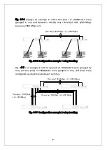
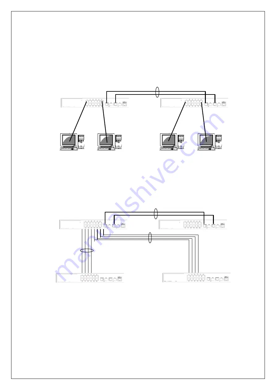
Fig. 4-7-6 displays an example in which two ports of 1000BASE-T were
grouped in one and between switches was connected with 2000 Mbps
(one-way 1000 Mbps x 2).
Fig. 4-7-6 Configuration example 1 using trunking
Fig. 4-7-7 is an example in which four ports of 100BASE-TX were grouped by
two, and two ports of 1000BASE-T were grouped in one, and these were
configured as a backbone between switches.
Fig. 4-7-7 Configuration example 2 using trunking
One-way 1000 Mbps × 2 = 2000 Mbps
One-way 1000 Mbps × 2 = 2000 Mbps
One-way 100 Mbps
x 4 = 400 Mbps
One-way 100 Mbps × 4 = 400 Mbps
Summary of Contents for Switch-M12PWR
Page 17: ...17 Fig 2 2 Mounting to Wall ...
Page 20: ...20 function does not work Therefore use a cross cable to connect them ...
Page 30: ...30 ...
Page 36: ...36 ...
Page 49: ...49 ...
Page 69: ...69 ...
Page 81: ...81 setting and the management VLAN status of VLAN ID 1 is UP ...
Page 96: ...96 Press S Q Return to the previous menu ...
Page 98: ...98 ...
Page 122: ...122 Q Return to the previous menu ...
Page 125: ...125 ...
Page 130: ...130 ICMP Type Displays the ICMP type ...
Page 156: ...156 Threshold Displays the threshold of the number of packets per second ...
Page 173: ...173 Fig 4 7 49 Display of values accumulated after resetting the counters ...
Page 185: ...185 Q Return to the previous menu ...
Page 211: ...211 Q Return to the previous menu ...
Page 232: ...232 IEEE8021 PAE MIB IEEE802 1X IEEE8023 LAG MIB IEEE 802 3ad ...
Page 237: ...237 IEEE 802 3af standard ...
Page 240: ...240 P0813 1084 ...

