background image

Power Source :

AC AUTO 110-240V, 50/60 Hz

Power Consumption :

58W

Aerial Impedance :

75

Ω

unbalanced

Coaxial type

Receiving System :

17 Systems

Receiving Channels :

VHF

2-13(U.S.A Standard)

UHF

14-69(U.S.A Standard)

CATV

1-125(U.S.A Standard)

Audio Terminal :

DVD

Y

1.0 Vp-p, 75

Ω

PB

0.7 Vp-p, 75

Ω

PR

0.7 Vp-p, 75

Ω

AV 1, 2

Video In

1 Vp-p, 75

Ω

Audio In

Approx. 0.5V, 47k

Ω

Monitor Out

© 2007 Matsushita Electric Industrial Co., Ltd. All
rights

reserved.

Unauthorized

copying

and

distribution is a violation of law.

TC-21GX20P

GL1 Chassis

Video Out

1 Vp-p, 75

Ω

Audio Out

Approx. 0.5V, 1k

Ω

High Voltage :

27.5kV ±1.5

at zero beam current

Picture Tube :

A51LYZ395X65

50.5cm (21 inches)

Measured diagonally,

90° deflection

Audio Output :

5W + 5w = 10W

Dimensions :

Height : 472 mm

Width : 598 mm

Depth : 479 mm

Mass :

22.5 kg (Net Wt.)

Specifications are subject to change without notice.
Mass and dimensions shown are approximate.

Colour Television

Specifications

ORDER NO. MTV0701518CE

Summary of Contents for TC-21GX20P

Page 1: ...007 Matsushita Electric Industrial Co Ltd All rights reserved Unauthorized copying and distribution is a violation of law TC 21GX20P GL1 Chassis Video Out 1 Vp p 75 Audio Out Approx 0 5V 1k High Volta...

Page 2: ...vice Hints 5 2 1 Service Position for E Board 5 2 2 Factory Mode Adjustment 5 2 3 Adjustment for White Balance 8 2 4 Adjustment for CRT CUT OFF 8 2 5 Adjustment Procedure 9 2 6 Adjustment 10 3 Conduct...

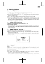
Page 3: ...sed metallic cabinet part on the receiver such as screw heads aerials connectors control shafts etc When the exposed metallic part has a return path to the chassis the reading should be between 4 M an...

Page 4: ...AW Rear Inputs AV1 V L R Front Inputs AV2 V L R YUV YUV CVBS4 CVBS2 IF V H V OUT H OUT R G B R G B CRT defl coil MONITOR OUT SDA SCL Audio Out Mon Out AUDIO AMP IC2302 IC601 UOC EEPROM IC1103 IC851 5V...

Page 5: ...nt a Set Timer ON 30 minutes Press remote s RECALL panel s vol down key simultaneously to select service mode b CHK should appear on right side of TV screen After few seconds CHK 1 should appear on ri...

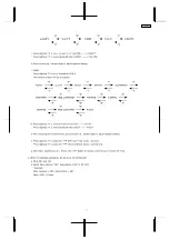
Page 6: ...ion will be as follows f Press digit key 4 to move forward from Colour Sub Colour etc Press digit key 3 to move backward from Sub Colour Colour etc g Press volume up volume down to adjust setting h Pr...

Page 7: ...e backward from G CUT R CUT n After selecting the required mode press volume up volume down to adjust required setting o Press digit key 5 to make the AKB OFF and H Line mode first time Press digit ke...

Page 8: ...FF so that X 0 233 0 015 nit 3 Adjustment G CUT OFF so that Y 0 235 0 015 nit Adjustment of High Light 1 Adjustment Sub Bright so that Y 150 nit 2 Adjustment R Drive so that X 0 262 0 010 nit 3 Adjust...

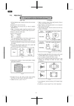
Page 9: ...follows TPA 10 141 1 5V TPA 12 3 3 0 5V TPA 09 5 1V 2 5 2 High Voltage Item preparation 1 Receive the crosshatch pattern 2 Set to 0 Beam Screen VR minimum Contrast minimum Adjustment procedure 1 Conn...

Page 10: ...ined Fig 21 10 Re adjust the Low Light controls to their correct settings and make sure that a uniform white field is obtained 11 Tighten the clamp screw A in Fig 10 Convergence 1 Apply a crosshatch p...

Page 11: ...primarily Fig 1 Purity magnet Set purity magnet that 2 magnets are TOP POSITION VRS magnet Set purity magnet 2 magnets are HORIZONTAL POSITION 2 Adjustment a Receive that Cross Hatch pattern b Adjust...

Page 12: ...and 3 shown in Fig 11 2 The wedges should be set 120 apart from each other 3 Be certain that three wedges are firmly fixed and the Deflection Yoke is tightly clamped in place Otherwise the Deflection...

Page 13: ...3 Conductor Views 13 TC 21GX20P...

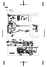
Page 14: ...4 Schematic Diagram 14 TC 21GX20P...

Page 15: ...15 TC 21GX20P...

Page 16: ...4 1 A Board 4 1 1 A Board 1 5 1A 2A 3A 5A 4A 6A 7A 8A 9A 16 TC 21GX20P...

Page 17: ...4 1 2 A Board 2 5 1B 2B 4B 3B 7B 6B 5B 8B 9B 1A 2A 3A 5A 4A 6A 7A 8A 9A 17 TC 21GX20P...

Page 18: ...4 1 3 A Board 3 5 1C 2C 4C 3C 7C 6C 5C 8C 9C 1B 2B 4B 3B 7B 6B 5B 8B 9B 18 TC 21GX20P...

Page 19: ...4 1 4 A Board 4 5 1D 2D 7D 4D 3D 8D 6D 5D 9D 1C 2C 4C 3C 7C 6C 5C 8C 9C 19 TC 21GX20P...

Page 20: ...4 1 5 A Board 5 5 1D 2D 7D 4D 3D 8D 6D 5D 9D 20 TC 21GX20P...

Page 21: ...4 2 L Board 4 2 1 L Board 1 3 1A 2A 3A 4A 5A 21 TC 21GX20P...

Page 22: ...4 2 2 L Board 2 3 1B 2B 3B 4B 5B 6B 1A 2A 3A 4A 5A 22 TC 21GX20P...

Page 23: ...4 2 3 L Board 3 3 1B 2B 3B 4B 5B 6B 23 TC 21GX20P...

Page 24: ...5 Parts Locations 24 TC 21GX20P...

Page 25: ...6 Replacement Parts List 25 TC 21GX20P...

Page 26: ...me Description Remarks C515 F1B2H331A025 C 330PF 500V C516 F2A1E102A199 E 1000UF 25V C519 F2A2C330A096 E 33UF 160V C520 F2A0J221A317 E 220UF 6 3V C550 ECQM4223JZ P 0 022UF J 400V C552 F2A2E1000023 E 1...

Page 27: ...1101 TALV35VB331K PEAKING COIL L2140 J0JKA0000038 BEAD CORE L3137 J0JKA0000024 EMI FILTER L350 J0JKA0000038 BEAD CORE L501 G0D820000005 LINEARITY COIL L550 J0JKB0000038 COIL L600 G0C100K00008 COIL L60...

Page 28: ...ER050CKF9532 M95 3KOHM F 1 2W R558 ERDS2TJ513 C 51KOHM J 1 4W R559 D0C12R7JA042 M 2 7OHM J 1W R560 ERG1SJ102E M 1KOHM J 1W R563 ERJ3GEY0R00 M 0OHM J 1 16W Ref No Part No Part Name Description Remarks...

Page 29: ...0OHM J 1 16W JSA123 ERJ3GEY0R00 M 0OHM J 1 16W JSA124 ERJ3GEY0R00 M 0OHM J 1 16W JSA3000 ERJ3GEY0R00 M 0OHM J 1 16W JSA3001 ERJ3GEY0R00 M 0OHM J 1 16W JSA3132 ERJ3GEY0R00 M 0OHM J 1 16W JSA3133 ERJ3G...

Reviews: