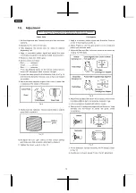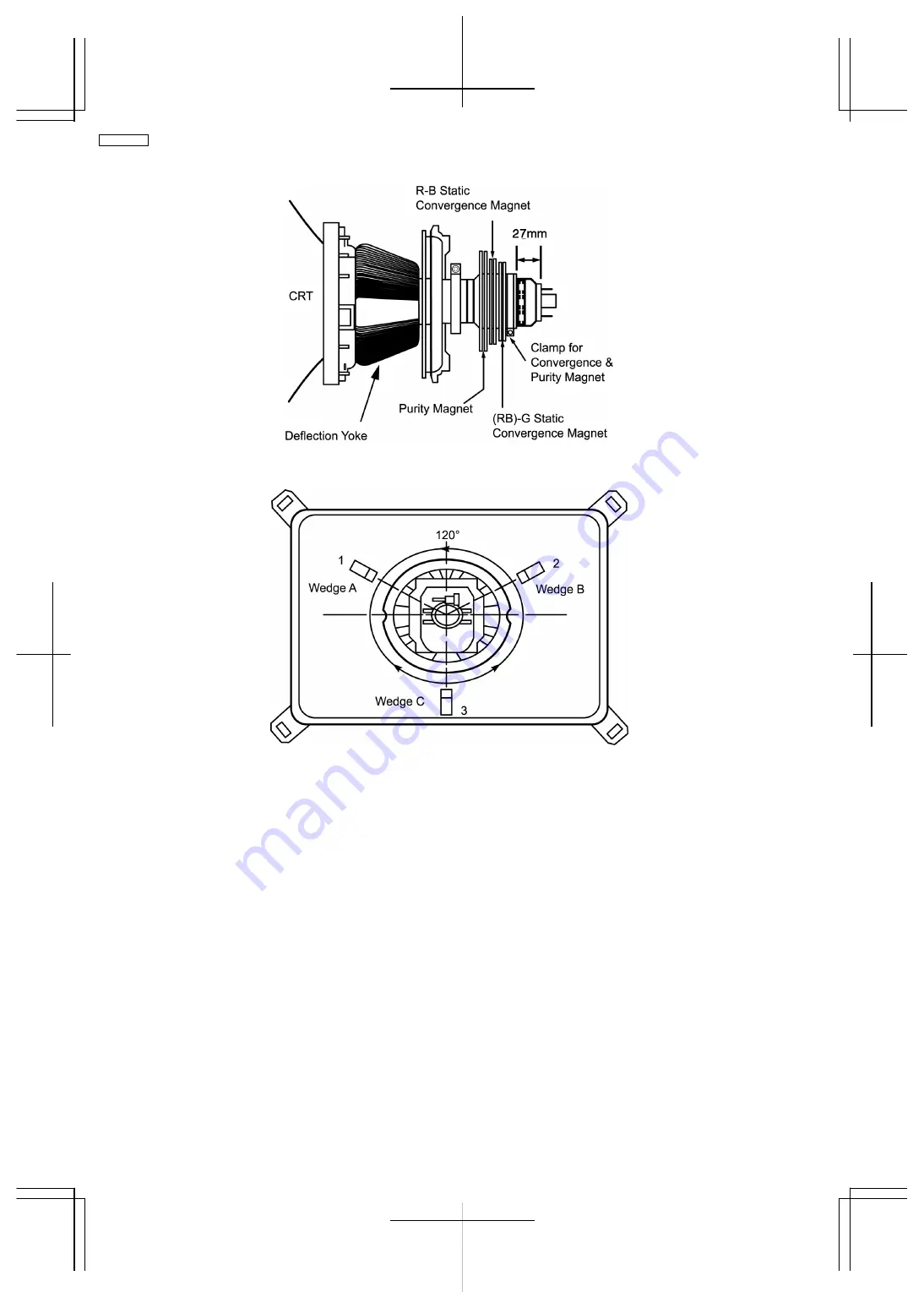
Fig. 10
Fig. 11
Notes:
1. Wedge A, B and C should be inserted following the sequence of 1, 2 and 3 shown in Fig. 11.
2. The wedges should be set 120° apart from each other.
3. Be certain that three wedges are firmly fixed and the Deflection Yoke is tightly clamped in place.
Otherwise the Deflection Yoke may shift its position and cause a loss of convergence and purity.
12
TC-21GX20P
Summary of Contents for TC-21GX20P
Page 13: ...3 Conductor Views 13 TC 21GX20P...
Page 14: ...4 Schematic Diagram 14 TC 21GX20P...
Page 15: ...15 TC 21GX20P...
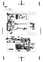
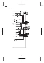
Page 16: ...4 1 A Board 4 1 1 A Board 1 5 1A 2A 3A 5A 4A 6A 7A 8A 9A 16 TC 21GX20P...
Page 17: ...4 1 2 A Board 2 5 1B 2B 4B 3B 7B 6B 5B 8B 9B 1A 2A 3A 5A 4A 6A 7A 8A 9A 17 TC 21GX20P...
Page 18: ...4 1 3 A Board 3 5 1C 2C 4C 3C 7C 6C 5C 8C 9C 1B 2B 4B 3B 7B 6B 5B 8B 9B 18 TC 21GX20P...
Page 19: ...4 1 4 A Board 4 5 1D 2D 7D 4D 3D 8D 6D 5D 9D 1C 2C 4C 3C 7C 6C 5C 8C 9C 19 TC 21GX20P...
Page 20: ...4 1 5 A Board 5 5 1D 2D 7D 4D 3D 8D 6D 5D 9D 20 TC 21GX20P...
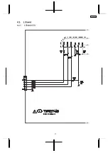
Page 21: ...4 2 L Board 4 2 1 L Board 1 3 1A 2A 3A 4A 5A 21 TC 21GX20P...
Page 22: ...4 2 2 L Board 2 3 1B 2B 3B 4B 5B 6B 1A 2A 3A 4A 5A 22 TC 21GX20P...
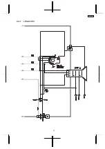
Page 23: ...4 2 3 L Board 3 3 1B 2B 3B 4B 5B 6B 23 TC 21GX20P...
Page 24: ...5 Parts Locations 24 TC 21GX20P...


