background image

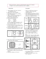
Adjustment for White Balance

Preparation :
1. Receive the white balance pattern and aging should have been performed over 30 minutes.
2. Set the picture menu to to DYNAMIC NORMAL.
3. Degause the CRT face.
4. Fix the CRT colour analyzer receiver unit to CRT face.
 

Adjustment of Low Light.

1. Adjustment Sub Bright, so that Y = 6.3 +- 1.0nit.
2. Adjust R-CUT OFF, so that X = 0.235 +- 0.01nit.
3. Adjust G-CUT OFF, so that y = 0.235 +- 0.01nit.

Adjustment of High Light.

1. Adjust Sub Bright, so that Y = 390 nit.
2. Adjust R-Drive, so that X = 0.259 +- 0.01nit.
3. Adjust B-Drive, so that y = 0.259 +- 0.01nit.

Adjustment for CRT CUT OFF.

Preparation :
1. Connect ocilloscope probe to TPL7.
2. Screen VR min.
3. Set the data Sub Bright , Bright.
4. In service Mode at ‘Bright’ dac press [5] in factory mode to enter vertical line and adjust by    
    volume down or up button. 
5. Adjust “Screen VR” until 1-H Line appears.
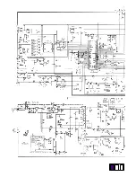
 

130V

0V

Summary of Contents for TC-21PM10R

Page 1: ... 1 12 NTSC M JAPAN Measured diagonally 90 deflection 2 13 NTSC M U S A UHF 21 69 PAL G H I SECAM G K K1 28 69 PAL B AUST Audio Output 2W x 2 4W 13 57 PAL D K 13 62 NTSC M JAPAN 14 69 NTSC M U S A CATV S1 S41 OSCAR Dimensions Height 373 5 mm 1 125 U S A CATV Width 485 0 mm C13 C41 JAPAN Depth 380 0 mm S21 S41 HYPER Z1 Z37 CHINA Mass 12 5 kg Intermediate Frequency Video 38 0 MHz Specifications are s...

Page 2: ...nly and is not designed for use by the general public It does not contain warning cautions to advise non technical individuals of potential dangers in attempting to service a product Product powered by electricity should be serviced or repaired only by experienced professional technicians Any attempt to service or repair the product or products dealt with in this service literature by anyone else ...

Page 3: ...re handling the tube After servicing make the following leakage current checks to prevent the customer from being exposed to shock hazards Leakage Current Cold Check 1 Unplug the AC cord and connect a jumper between the two prongs on the plug 2 Turn on the receiver s power switch Measure the resistance value with an ohmmeter between the jumper AC plug and each exposed metal lic cabinet part on the...

Page 4: ...lly calibrated high voltage meter 1 Set the brightness to minimum 2 Use the remocon to get into Service Mode 3 Measure the EHT The meter reading should indicate 27 5 1 0 kV If the meter indication is out of tolerance immediate service and correction is required to prevent the possibility of premature component failure 4 To prevent the possibility X Radiation it is essential to use the specifield p...

Page 5: ......

Page 6: ...nt How To Set To set the Factory mode press Volume 0 dac on the TV and Timer Setting 30min on the remote control and press Volume Down button on the TV together press recall on the remote control CHK should appear on right of TV screen To move from CHK1 to CHK2 mode etc please follow below rotation To Set Self Check Press the volume down button on TV than press the off timer button on remote contr...

Page 7: ... 2 Adjust R CUT OFF so that X 0 235 0 01nit 3 Adjust G CUT OFF so that y 0 235 0 01nit Adjustment of High Light 1 Adjust Sub Bright so that Y 390 nit 2 Adjust R Drive so that X 0 259 0 01nit 3 Adjust B Drive so that y 0 259 0 01nit Adjustment for CRT CUT OFF Preparation 1 Connect ocilloscope probe to TPL7 2 Screen VR min 3 Set the data Sub Bright Bright 4 In service Mode at Bright dac press 5 in f...

Page 8: ...GC at Tuner voltage drop High Voltage 1 Receive the crosshatch pattern 1 Connect a DC voltage meter to TPA 12 and confirm the B voltage is 141 2 0 8V 2 Set to 0 Beam 2 Connect a high frequency voltmeter to heater and Screen VR minimum confirm that voltage reads 6 0 0 24 VRMS Contrast minimum 3 Normalize the brightness and contrast Item Preparation Adjustment Produre Connect a short jumper between ...

Page 9: ...4 Connect TPA 10 to TPA 20 5 Set A to 2 3 0 2V by BRT CHK2 Fig 1 Adjustment 1 Connect oscilloscope probe to TPA 31 G OUT with 10k series resistor and adjust Contrast so that B as in Fig 1 is 2 8 0 1V 2 Adjust Sub Colour so that waveform as in Fig 1 1 2 5 0 1V 3 Connect oscilloscope probe to TPA 32 R OUT with 10k series resistor and confirm waveform as in Fig 2 is 2 2 7 0 4V Fig 1 Fig 2 B 1 A 2 A 0...

Page 10: ...e A in Fig 24 and move the deflection yoke as close to the purity magnet as possible 8 Adjust the purity magnetic rings so that a vertical green field is obtained at the cntre of the screen Fig 22 4 Adjust Red and Blue with Green line at centre of the screen by rotating RB G static convergence magnetic rings 5 Lock convergence magnetic with silicne sealer 6 Remove the DY wedges and slightly tilt t...

Page 11: ... from each other 3 Be certain that four wedges are firmly fixed and the Deflection Yoke is tightly clamped in place Otherwise the Deflection Yoke may shift its position and cause a loss of convergence and purity 25 4 mm R B Static Convergence Magnet Purity Magnet RB G Static Convergence Magnet Clamp for Convergence Purity Magnet Deflection Yoke ...

Page 12: ......

Page 13: ......

Page 14: ......

Page 15: ......

Page 16: ......

Page 17: ......

Page 18: ......

Page 19: ......

Page 20: ......

Page 21: ......

Page 22: ......

Page 23: ...r production discontinuation of the complete set Abbreviation of part name and description 1 Resistor 2 Capacitor Example Example ERD25TJ104 C 100KOHM J 1 4W ECKF1H103ZF C 0 01UF Z 50V Type Allowance Type Allowance Type Allowance Type Allowance C Carbon F 1 C Carbon C 0 25pF F Fuse G 2 E Electrolytic D 0 5pF M Metal Oxide J 5 P Polyester F 1pF Metal Film K 10 Polypropylene G 3 S Solid M 20 T Tanta...

Page 24: ...N63115 4 PURITY MAGNET R443 ERJ12YJ132U M 1 3KOHM J 1 2W 26 TSX4G111H AC POWER CORD R444 ERG1SJ182E M 1 8KOHM J 1W 27 TXFKY01RM4V CABINET ASSY R445 ERJ6GEYJ473 M 47KOHM J 1 10W TXFPD01QH2S CUSHION TOP R446 ERJ6GEYJ473 M 47KOHM J 1 10W TXFPD02QH2S CUSHION BOTTOM R447 ERJ6GEYJ472 M 4 7KOHM J 1 10W 28 TXFSA01AA2S DIPOLE ANTENNA R448 ERJ6GEYJ242 M 2 4KOHM J 1 10W RESISTORS R449 ERJ6GEYJ152 M 1 5KOHM J...

Page 25: ... M 560OHM J 1 10W R1101 ERJ6GEYJ332 M 3 3KOHM J 1 10W R636 ERJ6GEYJ562 M 5 6KOHM J 1 10W R1102 ERJ6GEYJ153 M 15KOHM J 1 10W R637 ERJ6GEYJ473 M 47KOHM J 1 10W R1103 ERJ6GEYJ103 M 10KOHM J 1 10W R638 ERJ6GEYJ391 M 390OHM J 1 10W R1104 ERJ6GEYJ562 M 5 6KOHM J 1 10W R639 ERJ6GEYJ101 M 100OHM J 1 10W R1105 ERJ6GEYJ562 M 5 6KOHM J 1 10W R640 ERJ6GEYJ181 M 180OHM J 1 10W R1106 ERJ6GEYJ102 M 1KOHM J 1 10W...

Page 26: ...Z 16V C109 ECJ2VF1H103Z C 0 01UF Z 50V C634 ECJ2ZF1C105Z C 1UF Z 16V C116 ECJ2VF1H103Z C 0 01UF Z 50V C635 ECJ2VF1H104Z C 0 1UF Z 50V C117 ECJ2VB1H103J C 0 01UF 50V C636 ECEA1CKA101 E 100UF 16V C120 ECJ2VF1H103Z C 0 01UF Z 50V C639 ECA1HM220B E 22UF 50V C121 ECJ2VF1H103Z C 0 01UF Z 50V C641 ECJ2VC1H100C C 10PF C 50V C122 ECJ2VF1H103Z C 0 01UF Z 50V C653 ECEA1CKA100 E 10UF 16V C136 ECJ2VF1H103Z C 0...

Page 27: ...53 ECA1CM100B E 10UF 16V D511 MA4108J DIODE C2354 ECA1CM471B E 470UF 16V D512 MA171 DIODE C2357 ECEA1HKN010 E 1UF 50V D520 MA152KTX DIODE C2380 ECA1CM101B E 100UF 16V D551 MA3047HTX DIODE C2401 ECJ2VB1H682K C 6800PF K 50V D552 D1FL40F4063 DIODE C2402 ECJ2ZF1C105Z C 1UF Z 16V D555 MA152KTX DIODE C2403 ECJ2ZF1C105Z C 1UF Z 16V D556 ERD07 15 DIODE C2404 ECJ2VB1E104K C 0 1UF K 25V D557 TVSRU2AM DIODE ...

Page 28: ...KT TRANSISTOR JS41 ERJ6GEY0R00 M 0OHM J 1 10W Q102 2SC4787 TRANSISTOR JS42 ERJ6GEY0R00 M 0OHM J 1 10W Q103 2SD2114KT TRANSISTOR JS551 ERJ6GEY0R00 M 0OHM J 1 10W Q105 2SC2412KT TRANSISTOR JS2201 ERJ6GEY0R00 M 0OHM J 1 10W Q180 2SA1037AKT TRANSISTOR JS2202 ERJ6GEY0R00 M 0OHM J 1 10W Q369 2SA564AQR TRANSISTOR JS2205 ERJ6GEY0R00 M 0OHM J 1 10W Q401 2SA1037AKT TRANSISTOR JS3010 ERJ6GEY0R00 M 0OHM J 1 1...

Reviews: