- 24 -
TC-20G12P / TC-29G12P / TC-29G12PU
Service Adjustments and Calibrations
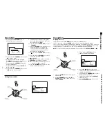
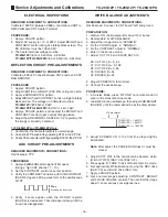
3. Set the White Balance pattern to over side the White Ba-
lance Meter. Adjust the G high light to 80µA by changing
SUB-BRIGHT (DAC: B2). If can not get 80µA, connect a
jumper through the cable between TP38 and TP41.
4. Then, adjust the R high light (DAC: C3) and the B
(DAC: C4) to zero on the White Balance Meter.
5. If the indication of the high light adjust on White Balance
Meter still doesnt get 80µ A, adjust the bright control to
the maximum.
6. Check the White Balance Meter under side , if it isnt
property , readjust the low light on standard window.
If the error of R is ± 5µ A and B is 10µ A repeat the
procedure 1 and 2.
7. Exit to the normal mode.
Note
: Adjust the White Balance using equipment adjusted
to colour temperature 10.800K
°
+ 19MPCD.
COLOR KILLER VERIFICATION
PREPARATION:
1. Adjust the color control to level 50.
PROCEDURE:
1. Apply a pattern signal with 40dB.
2. Verify to not appear color noises on any B/W channel.
3. Verify that the color doesnt disappear on any color
channel.
FILAMENT VOLTAGE CHECK UP
REQUIRED EQUIPMENTS / CONNECTIONS:
RMS Voltmeter: CRT filament terminal.
PROCEDURE:
1. Apply crosshatch pattern.
2. The filament voltage must be:
TC-20G12P
→
6,15V+0.40Vrms _0.24Vrms
TC-29G12P/TC-29G12PU
→
6,3V+0.40Vrms _0.24Vrms
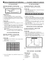
SUB BRIGHT ADJUSTMENT
PREPARATION:
Adjust CONTRAST to maximum and BRIGHT to center.
PROCEDURE:
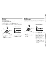
1. Apply standard SUB BRIGHT.
2. Adjust SUB BRIGHT (DAC: B2) to the central part of
PART 6 and PART 7 become black.
(PART 7=Black and PART 6=lightly illuminated).
4
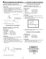
FOCUS ADJUSTMENT
PREPARATION:
1. Adjust CONTRAST to maximum and BRIGHT to center.
PROCEDURE:
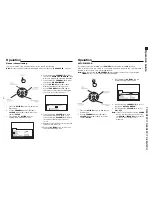
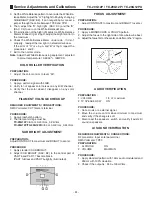
1. Apply a MONOSCOPE or PHILIPS pattern.
2. Adjust the focus to the right side of draw below be best.
3. Adjust the focus, first on the center, and after on the 4 region.
AUDIO VERIFICATION
PREPARATION :
1. VOLUME
1/3 of maximum
2. TV SPEAKER SW
ON
PROCEDURE:
1. Set a music or a external signal.
2. Move the volume control since minimum to maximum
and verify if the change is soft.
3. Disconnect the speakers switch and verify if exist still
sound on speakers.
AI SOUND VERIFICATION
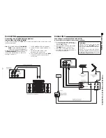
REQUIRED EQUIPMENTS / CONNECTIONS:
RF Generator: Input antenna terminal
RMS Voltmeter: TP83
PREPARATION:
1. AI SOUND ON
2. VOLUME MAXIMUN
PROCEDURE:
1. Apply standard pattern with 1KHz audio modulated and
25KHz with 100% deviation.
2. Check if the output is : 240 ± 100mVrms.
Summary of Contents for TC-29G12P
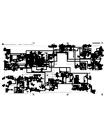
Page 27: ...27 TC 20G12P TC 29G12P TC 29G12PU Main Board Schematic Diagram TC 20G12P TC 29G12P TC 29G12PU...
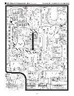
Page 31: ...31 TC 20G12P TC 29G12P TC 29G12PU A C Board Components side Top view...
Page 32: ...32 TC 20G12P TC 29G12P TC 29G12PU A C Board Foil side Bottom view...
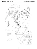
Page 33: ...33 TC 29G12P TC 29G12PU Cabinet Parts Location...
Page 41: ......
Page 42: ...Panasonic do Brasil Ltda CS GROUP TECHNICAL SUPPORT...

