background image

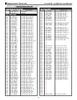
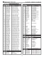
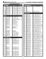
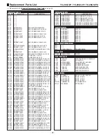
Replacement Parts List

- 36 -

TC-20G12P / TC-29G12P / TC-29G12PU

REF. NO.

CAPACITORS

PART NO.

DESCRIPTION

REF. NO.

DIODES

PART NO.

DESCRIPTION

C804

ECKWAE472ZED

CAP. CER. 4,70 nF 250 V

C805

ECKR1H471KB6

CAP. CER. 470 PF 50 V

C806

ECKWAE472ZED

CAP. CER. 4,70 nF 250 V

C807

ECKWAE472ZED

CAP. CER. 4,70 nF 250 V

C810

ECKCNA152MEB

CAP. CER. 1,50 nF 4.000 V

C811

ECA1EM101B

CAP. ELETROL. 100 µF 25 V

C812

ECQU2A224MNB

CAP. POLIPROP. 220 nF 100 V

C814

ECKR2H561KB7

CAP. CER. 560 PF 500 V

C816

ECKW3D331JBP

CAP. CER. 330 PF 2.000 V

C823

ECEA160V33ZE

CAP. ELETROL. 33 µF 160 V

C824

(

S

)

C854

ECJ2VB1E104K

CAP. CER. SMD 100 nF 25 V

C855

ECKW3A821KBP

CAP. CER. 820 PF 1.000 V

C856

ECKR2H561KB8

CAP. CER. 560 PF 500 V

C857

ECKR2H471KB5

CAP. CER. 470 PF 500 V

C859

ECA1EM102GB

CAP. ELETROL. 1.000 µF 25 V

C861

ECA1EM101B

CAP. ELETROL. 100 µF 25 V

C865

EC0S2DG151DG

CAP. ELETROL. 150 µF 200 V

C2201

ECSF16E3R3VB

CAP. TÂNTALO 3,30 µF 16 V

C2202

ECA1EM4R7B

CAP. ELETROL. 4,70 µF 25 V

C2203

ECA1HM010B

CAP. ELETROL. 1 µF 50 V

C2204

ECA1EM4R7B

CAP. ELETROL. 4,70 µF 25 V

C2205

ECA1EM4R7B

CAP. ELETROL. 4,70 µF 25 V

C2206

ECA1EM4R7B

CAP. ELETROL. 4,70 µF 25 V

C2207

ECA1EM4R7B

CAP. ELETROL. 4,70 µF 25 V

C2208

ECA1EM4R7B

CAP. ELETROL. 4,70 µF 25 V

C2209

ECA1AM101B

CAP. ELETROL. 100 µF 10 V

C2210

ECA1HMR33B

CAP. ELETROL. 0,33 µF 50 V

C2211

ECEA1HUR68B

CAP. ELETROL. 0,68 µF 50 V

C2212

ECA1HM2R2B

CAP. ELETROL. 2,20 µF 50 V

C2213

ECA1EM100B

CAP. ELETROL. 10 µF 25 V

C2214

ECQB1H104JM3

CAP. POLIÉSTER 100 nF 50 V

C2215

ECQB1H223JM3

CAP. POLIÉSTER 22 nF 50 V

C2216

ECJ2VB1H332K

CAP. CER. SMD 3,30 nF 50 V

C2217

ECEA1HN010UB

CAP. ELETROL. BIP. 1 µF 50 V

C2218

ECEA1HN010UB

CAP. ELETROL. BIP. 1 µF 50 V

C2219

ECSF16E10VB

CAP. TÂNTALO 10 µF 16 V

C2220

ECEA1CN100UB

CAP. ELETROL. BIP. 10 µF 16 V

C2221

ECJ2VB1H103K

CAP. CER. SMD 10 nF 50 V

C2222

ECJ2VB1H472K

CAP. CER. SMD 4.700 PF 50 V

C2302

ECA1HM3R3B

CAP. ELETROL. 3,30 µF 50 V

C2303

ECA1HM100B

CAP. ELETROL. 10 µF 50 V

C2304

ECQB1H104JM4

CAP. POLIÉSTER 100 nF 50 V

C2305

ECJ2VB1H332K

CAP. CER. SMD 3,30 nF 50 V

C2306

ECA1CM221B

CAP. ELETROL. 220 µF 16 V

C2307

ECEA1HN010UB

CAP. ELETROL. BIP. 1 µF 50 V

C2308

ECA1HHG010B

CAP. ELETROL. 1 µF 50 V

C2311

ECA1HM3R3B

CAP. ELETROL. 3,30 µF 50 V

C2351

ECA1EM102GB

CAP. ELETROL. 1.000 µF 25 V

C2352

ECA1HHG3R3B

CAP. ELETROL. 3,30 µF 50 V

C2353

ECA1HHG100B

CAP. ELETROL. 10 µF 50 V

C2354

ECQB1H104JM5

CAP. POLIÉSTER 100 nF 50 V

C2355

ECJ2VB1H332K

CAP. CER. SMD 3,30 nF 50 V

C2356

ECA1CHG221B

CAP. ELETROL. 220 µF 16 V

C2357

ECEA1HN010UB

CAP. ELETROL. BIP. 1 µF 50 V

C2451

ECA1EM100B

CAP. ELETROL. 10 µF 25 V

C2452

ECA1EM100B

CAP. ELETROL. 10 µF 25 V

C2453

ECA1EM4R7B

CAP. ELETROL. 4,70 µF 25 V

C2454

ECA1CM221B

CAP. ELETROL. 220 µF 16 V

C3001

ECA1HM010B

CAP. ELETROL. 1 µF 50 V

C3002

ECA1HM010B

CAP. ELETROL. 1 µF 50 V

C3003

ECA1HM010B

CAP. ELETROL. 1 µF 50 V

C3004

ECJ2VB1H272K

CAP. CER. SMD 2,70 nF 50 V

C3005

ECJ2VB1H272K

CAP. CER. SMD 2,70 nF 50 V

D001

EL333ID-F45R

LED DIODE

D006

MA4330HTA

ZENER  DIODE 34 V 0,37 W

D008

MA165TA5VT

SWITCHING DIODE

D010

MA4047HTA

ZENER DIODE 4,7 V 0,37 W

D012

MA165TA5VT

SWITCHING DIODE

D013

MA4068MTA

ZENER DIODE 6,8 V 1/4 W

D014

MA165TA5VT

SWITCHING DIODE

D2301

MA165TA5VT

SWITCHING DIODE

D2302

MA165TA5VT

SWITCHING DIODE

D2304

MA4068MTA

ZENER DIODE 6,8 V 1/4 W

D3001

MA4110MTA

ZENER DIODE 11 V 0,37 W

D3002

MA4110MTA

ZENER DIODE 11 V 0,37 W

D3003

MA4110MTA

ZENER DIODE 11 V 0,37 W

D401

ERA1501V3

SWITCHING DIODE

D402

MA4360MTA

ZENER DIODE 36 V 0,37 W

D403

MTZJT-774.7C

ZENER DIODE 4,7 V 0,5 W

D404

MA165TA5VT

SWITCHING DIODE

D405

MTZJT-7736D

ZENER DIODE 36 V 0,5 W

D406

MA165TA5VT

SWITCHING DIODE

D407

MA4051HTA

ZENER DIODE 5,3 V 0,37 W

D510

EU2V1

RECTIFY DIODE

D511

MTZJT-775.6A

ZENER DIODE 5,4 V 1/2 W

D551

RU2NV1

DIODE

D552

AU02V0

POWER DIODE

D554

AU02V1

POWER DIODE

D558

(

S

)

D559

(

S

)

D602

MA165TA5VT

SWITCHING DIODE

D751

(

S

)

D752

(

S

)

D801

(

S

)

D802

D4SB80

RECTIFY DIODE

D803

EU02V1

RECTIFY DIODE

D804

EU02V2

RECTIFY DIODE

D805

(

S

)

D808

MA165TA5VT

SWITCHING DIODE

D810

MTZJT-776.8C

ZENER DIODE 6,8 V 0,5 W

D811

AM01AV0

RECTIFY DIODE

D812

EU02V3

RECTIFY DIODE

D814

MA2240-BLFS

ZENER DIODE 24 V 1 W

D821

PC123F2

FOTO ACOPLADOR

D837

RU3YX-MV1

RECTIFY DIODE

D852

RL30A

RECTIFY DIODE

D855

EU2V2

RECTIFY DIODE

F801

XBA2C40TR0

FUSE 4A 250V

IC001

MN1874083TK2

IC MICROPROCESSOR

IC002

S-24C08ADP

IC EEPROM  ( 8K )

IC003

RPM6937-V13

IC MONOLITIC

IC2201

AN5819K

IC

IC2202

AN78L09TA

IC MONOLITIC

IC2303

LA4285

IC MONOLITIC

IC2451

AN5285K

IC SOUND AGC

IC401

LA7840

IC VERTICAL-OUT

IC402

BA225

IC

IC551

AN78M09LB

IC REGULATOR

IC552

AN78M05LB

IC REGULATOR

IC601

M52770ASP700

IC MONOLITIC

IC602

AN78L09TA

IC MONOLITIC

IC801

(

S

)

IC802

SE130NLF4

IC VOLTAGE REGULATOR

J703

ERJ6GEY0R00V

RES. MET. FILM SMD 0 

 1/10 W

JA1

ERJ6GEY0R00V

RES. MET. FILM SMD 0 

 1/10 W

JA10

ERJ6GEY0R00V

RES. MET. FILM SMD 0 

 1/10 W

JA2

ERJ6GEY0R00V

RES. MET. FILM SMD 0 

 1/10 W

JA3

ERJ6GEY0R00V

RES. MET. FILM SMD 0 

 1/10 W

JA4

ERJ6GEY0R00V

RES. MET. FILM SMD 0 

 1/10 W

DIODES

INTEGRATED CIRCUITS

FUSE

JUMPERS

(

S

) Please refer to the 

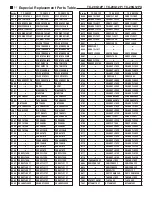
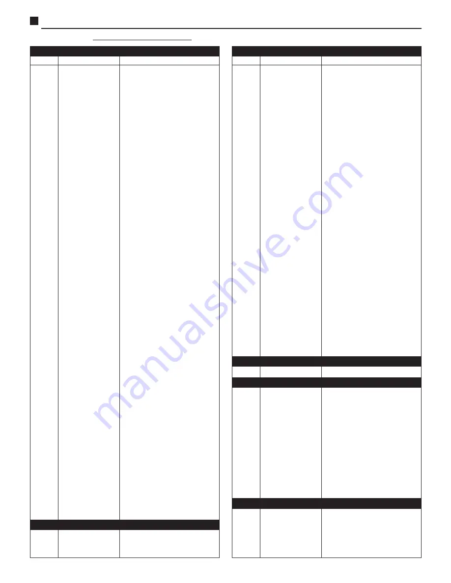
Especial Replacement Parts Table

 on page 40.

Summary of Contents for TC-29G12P

Page 1: ...eption Tuning system Audio power Video input Audio input Audio output Audio reception Visual diagonal Cinescope Dimensions W H D Weight Remote Control Transmiter Power Source 3V 2 R6 batteries Infrare...

Page 2: ...ure tube in addition to restricting magnetic effects When using a picture tube test jig for service ensure that the jig is capable of handling 31kV without causing X ray radiation Before returning a s...

Page 3: ...ra video game etc 10 Audio output P AMPLIF DE AUDIO Use this terminal to output audio to an external stereo amplifier Do not connect loudspeakers directly to this terminal 11 Power cable Controls Loca...

Page 4: ...n will be temporarily displayed on the screen When using the numerical keypad in CABLE mode to select channels 10 11 or 12 there is a delay before the channels are changed due to the VOLUME buttons Pr...

Page 5: ...iously set Channel identification if previously set R TUNE quick tune in button Use this button to alternate instantly between the two channels last selected Operation 1 Press the ACTION button to dis...

Page 6: ...adcast as such SAP According to audio program usually allows reception of audio that is broadcast in the original language MONO When the audio signal is broadcast through only one channel or when the...

Page 7: ...ay be that while adjusting contrast and brightness to minimum values the displayed menu becomes too dark If this happens press the ACTION and POWER on the TV set panel buttons simultaneously for at le...

Page 8: ...OTHER OPTIONS and a second page for adjustments will display 5 Press the CHANNEL button to select the CHANNEL function If the set is in video mode skip instructions 5 and 6 6 Using the VOLUME buttons...

Page 9: ...the set turns itself off after 90 minutes if there is no activation of any function during this period For the automatic turn off to occur the TV set must be turn on by PROGRAM TIMER ON and the funct...

Page 10: ...To deactivate the automatic on off timer select NO in step 13 14 Press the ACTION button twice to exit the timer adjustment menu Operation Adjusting the clock To adjust the clock the POWER button must...

Page 11: ...may be that while adjusting contrast and brightness to minimum values the displayed menu becomes too dark If this happens press the ACTION and POWER on the TV set panel buttons simultaneously for at l...

Page 12: ...le to tune in all channels that are locally broadcast These channels are the programmed channels and are selected through the CHANNEL buttons or 4 or through the numerical keypad on the remote control...

Page 13: ...nnel from memory yellow color 9 Repeat steps 7 and 8 to store or delete channels from memory 10 Press the ACTION button twice to exit the manual tuning menu Operation AUTO POWER ON For this function t...

Page 14: ...rperson DISPLAY T1 T4 idem C1 C4 has a different placement of the information T1 T4 displays in a black window positioned in the bottom half of the screen displaying the information corresponding to t...

Page 15: ...l 4 The sound level and the function MUTE may be accessed from the remote control unit Connection Connecting to a videocassette recorder VCR To connect to a videocassette recorder proceed as follows 1...

Page 16: ...ot mix new and used batteries 3 Do not mix different types of batteries for example carbon zinc with alkaline batteries 4 Do not attempt to charge short circuit open warm up or burn used batteries 5 R...

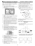
Page 17: ...lter among CHQ s B0 C0 S0 M0 press POWER 5 To alter among DAC s B0 B1 and C0 C1 press CH or CH _ and to alter the values press VOL or Vol _ 6 To get access to contents of directions of the memory addr...

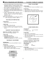
Page 18: ...al 75 open Using a high VHF channel 7 13 2 Set the CONTRAST control on center position 3 Verify the CONTRAST variation with SUB CONTRAST DAC B 3 to get a 3 0Vp p wave form on the oscilloscope at TP2 4...

Page 19: ...OLOUR BAR pattern of 63 2dB 75 open in the antenna terminal Using a high VHF channel 7 13 2 Confirm a normal image 3 Check if the noises disappear when the RF AGC register DCA Ca is decreased and note...

Page 20: ...l to the wave form doesn t be compressed 5 Adjust the SUB COLOR DAC B0 to obtain B as showed below 6 Remove the jumper on TP38 A NTSC SUB TINT ADJUSTMENT REQUIRED EQUIPMENTS CONNECTIONS Oscilloscope C...

Page 21: ...D RMS meter Between TP18 MPX in and GND Note The GND of oscilloscope must be next of IC2201 01 terminal for minimum noise 60 _30 PROCEDURE 1 Apply the next signal to antenna input RF Video 100 IRE Fla...

Page 22: ...URE 1 Measure TP42 for period 2 Adjust the register DAC S0 based in the next formula DAC S0 128 0 901x106 1 1 244 1406xTP42 3 Or measure TP42 for frequency 4 Adjust the register DAC S0 based in the ne...

Page 23: ...illoscope PROCEDURE 1 On service mode press R TUNE on remote control to enter to horizontal line mode 2 See GK on the oscilloscope screen then adjust SUB BRIGTH DAC B2 to raster period be as showed be...

Page 24: ...UIRED EQUIPMENTS CONNECTIONS RMS Voltmeter CRT filament terminal PROCEDURE 1 Apply crosshatch pattern 2 The filament voltage must be TC 20G12P 6 15V 0 40Vrms _0 24Vrms TC 29G12P TC 29G12PU 6 3V 0 40Vr...

Page 25: ...proportions to blue and green figure below 3 5 Slowly move the deflection coil forward until an uniform red is obtained completing the whole screen 3 6 Fix the deflection coil in place 3 7 Keep RECAL...

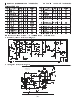
Page 26: ...UB CONTRAST SUB SHARPNESS V SIZE V CENTER V CENTER offset R CUT OFF G CUT OFF B CUT OFF R DRIVE B DRIVE R DRIVE warm B DRIVE warm R DRIVE cool B DRIVE cool AFT RF AGC RF AGC offset H CENTER H CENTER o...

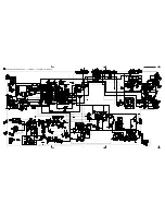
Page 27: ...27 TC 20G12P TC 29G12P TC 29G12PU Main Board Schematic Diagram TC 20G12P TC 29G12P TC 29G12PU...

Page 28: ...e oscilloscope of wide band and low capacity test points 1 to 10 The form and peak amplitude may vary depending on the oscilloscope and it s adjustment 01 IC601 Pin 12 02 IC601 Pin 14 03 IC601 Pin 15...

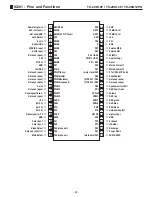
Page 29: ...41 40 39 38 37 36 35 34 33 GND 12MHz X tal 12MHz X tal 5V SCL SDA Version MSB Version GM 50 60Hz V pulse neg Reset Main AV select 1 Main AV select 2 X tal PAL M PAL N Sound defeat Not used open Not u...

Page 30: ...o e croma 32 AFC2 FILTER DC 4 5V AFC2 FILTER 33 CHROMA IN DC 3 5V CHROMA input 34 ID FILTER Identification filter 35 VIDEO IN DC 2 7V Video input 36 X RAY IN DC 0V X RAY in 38 BLACK HOLD DC 3 1V Black...

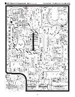
Page 31: ...31 TC 20G12P TC 29G12P TC 29G12PU A C Board Components side Top view...

Page 32: ...32 TC 20G12P TC 29G12P TC 29G12PU A C Board Foil side Bottom view...

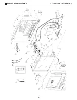
Page 33: ...33 TC 29G12P TC 29G12PU Cabinet Parts Location...

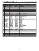
Page 34: ...61 1 TKP2B11161 1 TKP2B11161 1 AC CABLE HOLDER 17 TKY2B0906 4 TKY2B1304 3 TKY2B1304 3 CABINET 19 TKK2B0304 TKK2B0303 TKK2B0303 LED GUIDE 20 _o_ EXCELSA35T EXCELSA35T MAGNET 26 ENV56D75G3R ENV56D75G3R...

Page 35: ...22B CAP ELETROL 0 22 F 50 V C408 ECJ2VC1H102J CAP CER SMD 1 nF 50 V C409 ECJ2VF1H103Z CAP CER SMD 10 nF 50 V C451 ECQE1224KF3 CAP POLI STER 220 nF 100 V C452 EEUFC1V820B CAP ELETROL 82 F 35 V C453 ECQ...

Page 36: ...56 ECA1CHG221B CAP ELETROL 220 F 16 V C2357 ECEA1HN010UB CAP ELETROL BIP 1 F 50 V C2451 ECA1EM100B CAP ELETROL 10 F 25 V C2452 ECA1EM100B CAP ELETROL 10 F 25 V C2453 ECA1EM4R7B CAP ELETROL 4 70 F 25 V...

Page 37: ...ERDS2TJ562T RES CARBON 5 60 k 1 4 W R004 ERDS2TJ561T RES CARBON 560 1 4 W R005 ERDS2TJ101T RES CARBON 100 1 4 W R006 ERJ6GEYJ391V RES MET FILM SMD 390 1 10 W R007 ERJ6GEYJ561V RES MET FILM SMD 560 1...

Page 38: ...1 10 W R510 ERJ6GEYJ563V RES MET FILM SMD 56 k 1 10 W R511 ERJ6GEYJ473V RES MET FILM SMD 47 k 1 10 W R512 S R513 ERJ6GEYJ152V RES MET FILM SMD 1 50 k 1 8 W R514 ERJ6GEY0R00V RES MET FILM SMD 0 1 10 W...

Page 39: ...D 68 k 1 10 W R2314 ERJ6GEYJ104V RES MET FILM SMD 100 k 1 10 W R2315 ERJ6GEY0R00V RES MET FILM SMD 0 1 10 W R2317 ERDS2TJ561T RES CARBON 560 1 4 W R2318 ERJ6GEYJ103V RES MET FILM SMD 10 k 1 10 W R2319...

Page 40: ...362 ERDS2TJ822T ERDS2TJ272T ERDS2TJ272T R402 ERJ6GEYJ393V ERJ6GEYJ333V ERJ6GEYJ333V Ref No TC 20G12P TC 29G12P TC 29G12PU R406 ERDS1FJ1R5P ERDS1FJ1R0P ERDS1FJ1R0P R407 ERJ6GEYJ562V ERJ6GEYJ332V ERJ6GE...

Page 41: ......

Page 42: ...Panasonic do Brasil Ltda CS GROUP TECHNICAL SUPPORT...

Reviews: