18
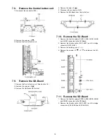
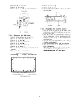
3. Remove the Adjustment cover.
4. Remove the screws (
×
4 ,
×
3 ,
×
1 ).
5. Remove the Rear terminal cover.
7.5.
Remove the Tuner unit
1. Unlock the cable clampers to free the cable.
2. Disconnect the connectors (A1, A6 A11, A12, A25 and
A30).
3. Disconnect the flexible cables (A31, A32 and A33).
4. Remove the screws (
×
2
) and remove the Tuner unit.
7.6.
Remove the A-Board
1. Remove the Tuner unit. (See section 7.5.)
2. Remove the screws (
×
4
) and remove the A-Board.
7.7.
Remove the Speakers
1. Unlock the cable clampers to free the cable.
2. Disconnect the relay connector.
3. Remove the screws (
×
2
) and remove the Speaker R.
4. Disconnect the connector (A12). (See section 7.5.)
5. Remove the screws (
×
2
) and remove the Speaker L.
Summary of Contents for TC-P50S1
Page 15: ...15 6 4 No Picture ...
Page 26: ...26 8 1 4 Adjustment Volume Location 8 1 5 Test Point Location ...
Page 28: ...28 ...
Page 34: ...34 ...
Page 36: ...36 10 3 Wiring 2 ...
Page 37: ...37 10 4 Wiring 3 ...
Page 38: ...38 10 5 Wiring 4 ...
Page 39: ...39 10 6 Wiring 5 ...
Page 40: ...40 ...
Page 41: ...41 11 Schematic Diagram 11 1 Schematic Diagram Note ...
Page 73: ...73 A B C D E F G H I 1 2 3 4 5 6 P BOARD COMPONENT SIDE ETX2MM747AFK ...
Page 86: ...86 ...
Page 88: ...88 13 1 2 Accessories ...
Page 89: ...89 13 1 3 Mechanical Replacement Parts List ...
Page 92: ...92 13 2 Electrical Replacement Parts List 13 2 1 Replacement Parts List Notes ...

