21
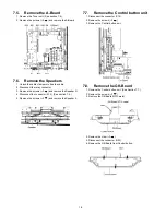
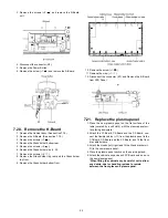
7.17. Remove the C3-Board
1. Remove the Tuner unit. (See section 7.4.)
2. Remove the Hanger metal L and the Stand bracket L.
(See section 7.14.)
3. Remove the flexible cables holder fastening screws (
×
8
).
4. Disconnect the flexible cables (CB8, CB9, CB10 and
CB11).
5. Disconnect the flexible cables (C31 and C32).
6. Disconnect the connectors (C33 and C35).
7. Remove the screws (
×
4
) and remove the C3-Board.
7.18. Remove the Plasma panel sec-
tion from the Cabinet assy
(glass)
1. Remove the cabinet assy and the plasma panel fastening
screws (
×
2 ).
2. For leaving the plasma panel from the front frame, pull the
bottom of the cabinet assy forward, lift, and remove.
3. Remove the Rear cover hooks (L, R).
7.19. Remove the S-Board
1. Remove the Cabinet assy. (See section 7.18.)
2. Remove the S-Board shield case.
Summary of Contents for TC-P50X1
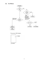
Page 15: ...15 6 4 No Picture ...
Page 25: ...25 8 1 4 Adjustment Volume Location 8 1 5 Test Point Location ...
Page 27: ...27 ...
Page 28: ...28 ...
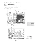
Page 34: ...34 10 3 Wiring 2 ...
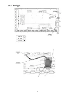
Page 35: ...35 10 4 Wiring 3 ...
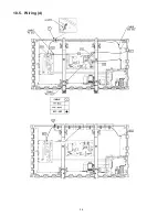
Page 36: ...36 10 5 Wiring 4 ...
Page 37: ...37 11 Schematic Diagram 11 1 Schematic Diagram Note ...
Page 69: ...69 A B C D E F G H I 1 2 3 4 5 6 P BOARD COMPONENT SIDE LSEP1279UNHB ...
Page 82: ...82 ...
Page 84: ...84 13 1 2 Accessories ...
Page 85: ...85 13 1 3 Mechanical Replacement Parts List ...
Page 88: ...88 13 2 Electrical Replacement Parts List 13 2 1 Replacement Parts List Notes ...

