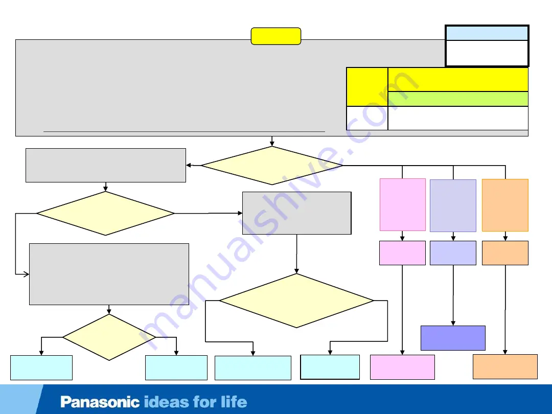
Slide 50
1.
Unplug the TV.
2.
Remove any residual charge from the Vsus and Vda lines. Use a 5W 500 ohms resistor.
3.
Measure the resistance between:
•
Chassis ground and pin 1 of connector P2 on the P board (Vsus).
•
Chassis ground and pin 12 of connector P6 on the P board (P15V).
•
Chassis ground and pin 1 of connector P35 on the P board (Vda).
Note:
A dead short or a reading lower than 1K indicates a shorted or partially shorted line.
Is there a short
circuit of the Vsus,
P15V, or Vda?
Yes
No
Shorted
P15V
Slide 50
Shorted
Vda
Continue on
next slide (C)
Shorted
Vsus
( 1 of 3)
Start Here
Continue on
next slide (A)
Continue on
next slide (B)
Unplug the TV and remove connector A1
from the A board. Plug in the TV and press
the power button.
Does the TV turn on
and stays on with the power
LED off?
Yes
No
Replace the
K board
Unplug the TV. Reconnect
A1 and disconnect the
Bluetooth module. Plug in
the TV but don’t turn it on.
OFF
Is the power LED
off or is it blinking 3
times continuously
at a fast pace ?
Replace the
Bluetooth module
Blinking
3 times
Unplug the TV and reconnect A1. Set your
voltmeter to measure DC voltage. Ground
the negative (Black) lead and place the
positive (Red) lead on pin 10 (F15V) of
connector P6 on the P board. Plug-in the
TV.
Does
15V
appears
briefly?
Replace the A
board
Yes
No
Replace the P
board
Shorted
pin 1
of
connector
P35
Shorted
pin 12
of
connector
P6
Shorted
pin 1
of
connector
P2
Applies to Models
TC-P55VT60
TC-P60VT60
Blink
Code
List of boards likely to cause this
symptom.
No specific order
3 Blinks
P, SS SC, A, K, Bluetooth module,
Cs, Panel
Troubleshooting 3 Fast Blinks Failure (TC-P55VT60
– TC-P60VT60)
Summary of Contents for TC-P55VT60
Page 4: ...Slide 4 Model Line Up and New Features and Technology ...
Page 6: ...Slide 6 2013 PDP Line up and Feature Comparison ...
Page 17: ...Slide 17 Boards Layout Functions and Part Numbers ...
Page 18: ...Slide 18 Board Layout Slide 18 TC P65ZT60 ...
Page 21: ...Board Layout TC P55VT60 TC P60VT60 Slide 21 Slide 21 TC P55VT60 TC P60VT60 ...
Page 22: ...Slide 22 PCB Location and Function ZT60 Series ...
Page 23: ...Slide 23 PCB Location and Function VT60 Series ...
Page 24: ...Slide 24 Service Tips ...
Page 26: ...Slide 26 Precautions to be Taken When Servicing the ZT60 Series TV ...
Page 27: ...Slide 27 Cable Binding Instructions ...
Page 34: ...Slide 34 Circuit Schematics ...
Page 36: ...Slide 36 Power Supply TC P60VT60 Slide 36 ...
Page 37: ...Slide 37 Power Supply TC P65VT60 TC P60ZT60 TC P65ZT60 Slide 37 ...
Page 38: ...Slide 38 TC P55VT60 TC P60VT60 TC P65VT60 TC P60ZT60 TC P65ZT60 P6 Pins Configuration ...
Page 39: ...Slide 39 Voltage Distribution TC P55VT60 TC P60VT60 TC P55 60VT60 ...
Page 40: ...Slide 40 Signal Processing Circuit ZT60 Series ...
Page 41: ...Slide 41 Signal Processing Circuit VT60 Series ...
Page 45: ...Slide 45 Troubleshooting Flowchart ...
Page 68: ...Slide 68 TV Data Copy to USB Drive ...
Page 74: ...Features Applications Slide ...
Page 75: ...My Home Screen Slide ...
Page 76: ...My Home Screen ZT60 VT60 ST60 ...
Page 78: ...My Home Screen ZT60 VT60 ST60 ...
Page 79: ...My Home Screen ZT60 VT60 ST60 ...
Page 81: ...VIERA Remote2 Slide ...
Page 91: ...Voice Interaction Slide ...
Page 92: ...Voice Interaction Allows Control of The TV Intuitively ...
Page 99: ...Electronic Touch Pen Slide ...
Page 105: ...Slide 105 End ...


