background image

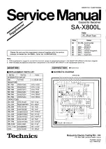
Summary of Contents for Technics SA-800

Page 1: ...SOCKET VOLTAGE ADJUSTER TECHNICAL SPECIFICATIONS SA 800 M MC SA 800 FE ES PHONO _2 5mV 47 kilohms Poe On ents a AUX 150mV 47 kilohms mags LoperRens Input sensitivity PLAYBACK TAPE 1 2 PLAYBACK TAPE 1...

Page 2: ...ECEA50M4R7R Electrolytic 4 7KF 50V C607 608 ECCD2HO70D ECCD2H120K Ceramic 12pF 500V 10 C613 614 ECCD2H820K Ceramic 82pF 500V 10 ECCD1H100K ECQU1A103MD M C1002 1003 ECQU1A103MD Polyester 0 01K F 125VAC...

Page 3: ...crew Lug Ground Screw Meter Bracket M tg Shaft Pulley Pulley Dial Bracket Meter Socket Power Transistors Washer Power Transistors Screw Screw Power Transistors M tg Terminal Speakers Left Terminal Spe...

Page 4: ...110V 120V 220V 240V C1003 0 01 AC LINE 110 120 220 240V 50 60Hz 1008 00 SWITCHED UNSWITCHED AC OUTLETS REC OUT R1007 47K PLAY BACK Wv REC OUT 7 PLAY BACK 5 REC OUT Ri008 47K PLAYBACK O REC OUT TAPE 2...

Page 5: ...RMS S N IHF A PHONO AUX Frequency response PHONO AUX 2 5mV 47 kilohms 150mV 47 kilohms 150mV 47 kilohms 200mV 83dB 97dB RIAA standard curve 0 2dB 0 20Hz 20k Hz _ 9308 0 _798 10Hz 40 kHz Tone controls...

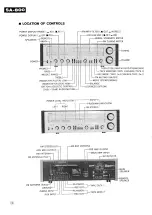
Page 6: ...2 SOURCE TAPE 2 1 FM MUTING ON OFF BOOST OFF FILTER LOW MODE STEREO MONO BOOST OFF FILTER HIGH OFF ON ACOUSTIC CONTROL 0dB 20dB AUDIO MUTING BALANCE LOUDNESS OFF ON POWER LEVEL INDICATOR LEFT RIGHT AM...

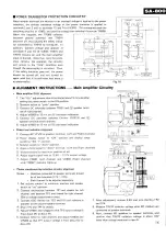
Page 7: ...lay drive circuitry and the tap selection relay RLY701 switches over to the low voltage tap When 80 speakers are connected to the MAIN and REMOTE speaker terminals and both speaker switches are on tot...

Page 8: ...d by way of D903 During the time that the TR904 collector is ground potential D903 becomes forward biased and therefore the comparator function is simultaneously reset when TR902 of the tap selection...

Page 9: ...eaker terminal of left channel 6 Adjust VR601 to 13 mV on DC voltmeter indication Power level indication alignment 1 Connect AC VTVM to speakers terminal Left and Right channels 2 Power display switch...

Page 10: ...terminal through 100 Mod 1OOMHz to speaker terminals Green Cot distortion meter FM dummy antenna with 400H 2 of receiver eer indication 4 Apply 60 dB to set FM MUTING LEVEL ALIGNMENT FM muting switch...

Page 11: ...sliding it toward the front of the set push forcefully from above 2 Fig 6 SA 800 SA 800 TERMINAL GUIDE 2SA979 SVTM47LP 2SA564 2SB536 2SD381 T101 2SA720 2SC828 FM IFT 2SC945 2SC1047 2SC1328 2SC 1675 A...

Page 12: ...pue a4 WYYD VIG 4OO1 8 241 3dvl ce LadVL SounNos 2 B3ONNOS 2 XNV 29 42 3dvVl cL 2 3dvl 31 CNOHd aes BGOW O3e S HOLINO W 3dVL 2S ee LNdLno CE WY il LNdLNO CO YOLOSI SS LS aa37 ae WOVEAW Id 33 2 Advi e...

Page 13: ...ot i 1 Teeoreve Or iwren ze poo a 8 o o l z 3 2 x 3 15 leg RANGE a fo Sol Net Va gs Soy te ie i 2 3 I nie 0 2 ar 3 8 S rece reoa 2 2S O ey o O oD a o o 2 8801802 TREOS B06 TREO SVDMZ2IGA 2Sa564 2SC828...

Page 14: ...ONE AMP TONE AME a AL O BQ0ST oe oe i a e o FILTER FILTER ACOUSTIC TREBLE LOW HIGH CONTROL MUTING LOUDNESS 2 100K B x2 S12 S10 ris 1 s8 z I i i fl S i To PRE QUT Roh 2 Leh To Tone Amp IN B Eguali Swit...

Page 15: ...TUNING 2 S 5 For threadi x 1 Prepare ww in length oe 2 Bring the s is comple LL x lowest frq Or4 O 3 Direct th TO TONE AMP 4 Stretch t elongated 5 Fix the k 4 fan S Pa ol _S m PACKIN w 2 mS w Sea OK...

Page 16: ...he knot of the cord with the bond my S S RS 2 m PACKINGS 3 P1 SPP545 aA oS co ee ad az iS SQF 1755 for America P4 SPS1383 P7 ene ad ek at Accessories P2 SPS1387 is SPS1381 P5S P3 SPS1385 2 Al SSA251 i...

Page 17: ...ont Knob Volume Knob Tuning Knob Selector Balance Treble Mid Range and Bass Nut Ornament M tg SYK457 XTN3 8BFZ SKU7030 SKX219 1 XTN3 14BFZ XTN3 8B SGX6549 SUS123 1 SBC 189 XNS8 XTN3 8B XTS3 8CFZ SGX65...

Page 18: ...rminal Speakers 2 Part No Part Name Description set OT XTN3 12B Screw Dial Scale Escutcheon M tg 2 SJF3421 Terminia Pre Out Main In o een SKD3390 Transparent Cover I 2 SJF 3223 Terminal 4CH Max Out an...

Page 19: ...50 Diode Driver Amplifier Circuit D605 606 SVDSTV4HG Diode Driver Amplifier Circuit Oo D607 LN35BP _ Light Emitting Diode O p70 SVDS15V 820 Rectifier e D702 M1120 Rectifier Relay Diod D705 706 SVDMZ33...

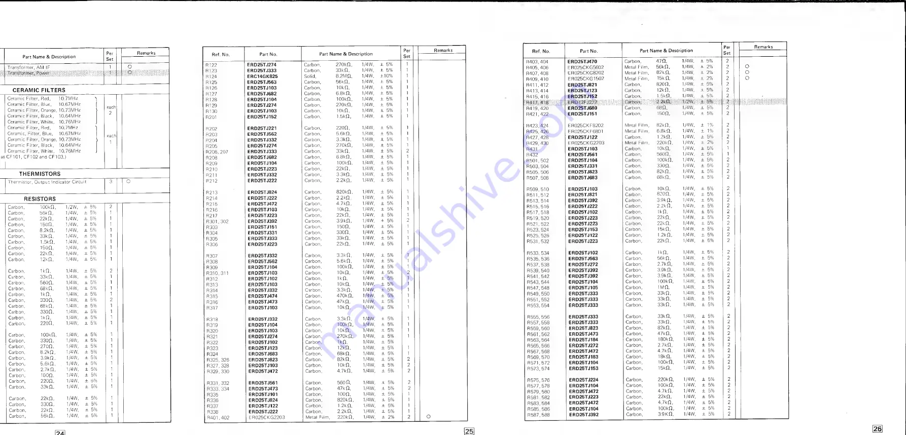
Page 20: ...R312 ERD25TJ102 Carbon 1k 5 1 R313 ERD25TJ103 Carbon 10kQ 5 1 R314 ERD25TJ332 Carbon 3 3k0 5 1 R315 ERD25TJ474 Carbon 470kQ 5 1 R316 ERD25TJ473 Carbon 47kQ 5 1 R317 ERD25TJ103 Carbon 10k 5 1 R318 ERD2...

Page 21: ...14 Main speakers switch in OFF position See page 10 15 15 Power display range switch in X1 position See page 13 SCHEMATIC DIAGRAM OF POWER LEVEL INDICATOR 16 16 Power source switch in OFF position See...

Page 22: ...Gleis zy i 8 a 2 Oy mor o fey o2le x 2 a Q 3 vR3 3 8 Qi FSRss g 100k8 8 jeje o ss 80 TREBLE IRS2t 22K LM f i AAA co 4 46 Uy as VR4 1 100KB R537 2 7k i R589 82M 3 1 MIDDLE ig 4 8 i es a fact 8 7 Ke x e...

Page 23: ...s vi eon C928 3 2 rd zoek 0 2 vo o 39 4 35V4 7 2 53 S8 4 3 VR3 2 R548 i RLY 601 ase ee 8 Lf RO7S 33K T TR 915 x TROIG ay 2 4 i s 2 R976 33K R538 i R969 3 3K a VR4 2 x cole a z 7 4 20 022 R590 34 x mex...

Page 24: ...R207 33K 7 7 foe neat 2 px 8 PHONO A lea R504 ceg2 5 cs 5 R203 5 6K D204 R205 270K D202 _ Ap 3 iE th tauxra 3 4 eh S wi 8 4 3 cea IrRs04 th J 5 x Fa rs 2 a Ta R204 3 3K R206 33K 0203 ofr C323 So eocae...

Page 25: ...3 ERD25TJ152 ERD25TJ392 ERD25TJ154 ERD25TJ154 ERD25TJ123 ERD25TJ471 ERD25TJ152 ERD25TJ393 ERD25TJ332 ERD25TJ122 ERD25TJ471 ERD25TJ123 ERD25TJ471 ERD25TJ101 ERD25TJ822 ERD25TJ563 ERD25TJ822 ERD25TJ333...

Page 26: ...50V Electrolytic O 22uF 50V Styrol A7OpF 5OV Polyester O0 015uF S0V Polyester 0 0015p F 50V Electrolytic 3 3uF 50V Electrolytic 3 3yuF 50V Electrolytic 47uF 16V Ceramic 470pF 50vV Electrolytic 3 3uF...

Page 27: ...TS LIST i SCHEMATIC DIAGRAM 1C61 1 C DOLBY NR R81 R82 ERDS2TI392 1 4W 3 9kQ R83 R84 1 4W 2 7kQ R85 R86 1 4W 47kQ R87 R88 ERDS2TJ561 1 4W 560Q R89 R90 ERDS2TJ224 1 4W 220kQ R91 R92 ERDS2TJ204 1 4W 200k...

Page 28: ...T SCHEMATIC DIAGRAM Ref No INTEGRATED CIRCUIT IC61 1 C DOLBY NR RESISTORS R81 R82 ERDS2TJ392 1 4W 3 9kQ R83 R84 ERDS2TJ272 1 4W 2 7kQ R85 R86 ERDS2TJ473 1 4W 47kQ R87 R88 ERDS2TU561 1 4W 5600 R89 R90...

Reviews: