TH-103PF10WK/TK/RK
17
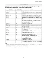
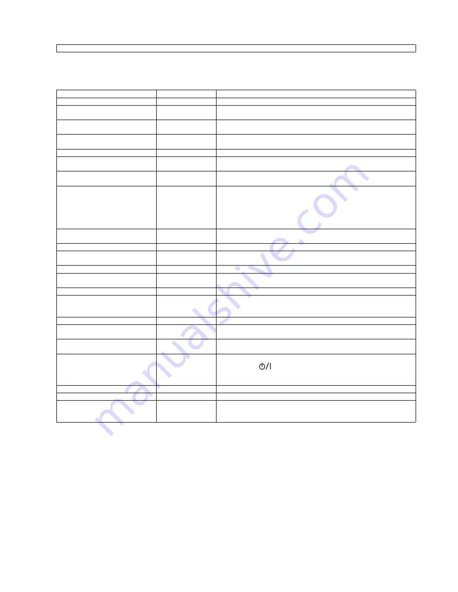
GPH10D chassis series have special function and operation setting facility called Option Menu. This Option Menu is use-
ful for special function required customers. This should be set at the installation stage.
Note:
When both main unit buttons and remote control are disabled due to the "Button lock", "Remocon User level" or "Remote ID"
adjustments, set all the values "Off" so that all the buttons are enabled again.
Press the "Volume down" button on main unit together with "R" button on the remote control and hold for more than 5 seconds.
The "SHIPPING" menu is displayed and the lock is released when it disappears.
Option Menu for GPF10D series
Option menus
default setting
Contents
Weekly Command Timer
---
Off-timer Sets Weekly Command Timer. Enable/Disable.
Onscreen display
On
Enable/Disable to display input mode indication after power on and no signal
indication.
Initial INPUT
Off
Sets the initial input mode when the power is turned on. Allow input mode selec-
tion while power is on.
Initial VOL level
Off
Sets the initial volume level when the power is turned on. Allow Volume control
while power is on.
Maximum VOL Level
Off
Sets the maximum volume to desired level. Volume cannot exceed this level.
INPUT lock
Off
Fixes the input mode to AV, Component/RGB or PC. Can not change input
mode by input selection key
Button lock
Off
Enable/Disable bottom operation buttons (Input, Menu, Enter and/or volume up/
down)
Remocon User Level
Off
Remote key invalidation.
Off: Valid key is all key of remote.
User1: Valid key are only Stand-by (ON/OFF), Input, Direct input, Status, Sur-
round, Sound mute On/Off, and volume adjustment.
User2: Valid key is only Stand-by (ON/OFF).
User3: All keys are null and void
Advanced PIP
Off
Off: Sets normal two screen display mode.
On: Sets Advanced PIP mode.
Off-timer function
Enable
Off-timer operation Enable/Disable.
Initial Power Mode
Normal
Sets the power mode of the unit for when the power recovers from failure or
after plugging off and in again.
ID select
0
Set ID number from 0 to 100.
Remote ID
Off
Remote ID function On/Off.
(While the Remote ID on, standard remote function can not control the unit.)
Serial ID
Off
Serial ID function On/Off
Display size
Off
Adjusts the image display size on screen.
On: Sets the image display size approximately 95% of the normal image dis-
play.
Studio W/B
Off
Set warm mode color temperature to 3,200 Kelvin.
Studio Gain
Off
Sharpens the contrast for a better view when a part of the image is too light to
see
Slot power
Off
Sets the slot power mode while the power is turned on.
Allow Optional Terminal Board insert Slots while power is on.
Power On Screen Delay
Off
You can set the power-on delay time of the displays to reduce the power load,
when you press
to turn on the multiple displays that are set together, for
example, on MULTI DISPLAY system.
Set each display’fs setting individually.
V. Installation
Off
V. Installation function On/Off (Not used)
Rotate
Off
The image rotates 180 degrees (up-down)
Serial Slot Select
Slot1
Selects the slot which communicates serial.
Note:
The setting of an external command can be set only from the fixed serial
terminal.
Summary of Contents for TH-103PF10WK
Page 6: ...TH 103PF10WK TK RK 6 3 Service Navigation 3 1 Service Hint ...
Page 8: ...TH 103PF10WK TK RK 8 3 2 Applicable signals ...
Page 9: ...TH 103PF10WK TK RK 9 ...
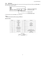
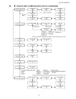
Page 15: ...TH 103PF10WK TK RK 15 5 2 IIC mode structure following items value is sample data ...
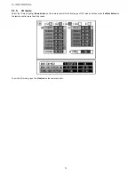
Page 16: ...TH 103PF10WK TK RK 16 5 3 Option Setting ...
Page 57: ...TH 103PF10WK TK RK 57 Structure of replacement Plasma Panel Spare Parts ...
Page 61: ...TH 103PF10WK TK RK 61 8 1 4 Adjustment Volume Location 8 1 5 Test Point Location ...
Page 63: ...TH 103PF10WK TK RK 63 ...
Page 65: ...TH 103PF10WK TK RK 65 ...
Page 67: ...TH 103PF10WK TK RK 67 9 Block Diagram 9 1 DiagramNote ...
Page 98: ...TH 103PF10WK TK RK 98 10 8 Lead Wiring 1 ...
Page 99: ...TH 103PF10WK TK RK 99 10 9 Lead Wiring 2 ...
Page 100: ...TH 103PF10WK TK RK 100 10 10 Lead Wiring 3 ...
Page 101: ...TH 103PF10WK TK RK 101 10 11 Lead Wiring 4 ...
Page 102: ...TH 103PF10WK TK RK 102 10 12 Lead Wiring 5 ...
Page 103: ...TH 103PF10WK TK RK 103 10 13 Lead Wiring 6 ...
Page 104: ...TH 103PF10WK TK RK 104 10 14 Lead Wiring 7 ...
Page 105: ...TH 103PF10WK TK RK 105 10 15 Lead Wiring 8 ...
Page 106: ...TH 103PF10WK TK RK 106 10 16 Lead Wiring 9 ...
Page 107: ...Model No TH 103PF10WK TK RK Caution ...
Page 108: ...Model No TH 103PF10WK TK RK Exploded View ...
Page 109: ...Model No TH 103PF10WK TK RK Side Power part location ...
Page 110: ...Model No TH 103PF10WK TK RK Cabinet part location ...
Page 111: ...Model No TH 103PF10WK TK RK Fan part location ...
Page 112: ...Model No TH 103PF10WK TK RK Rear cover location ...
Page 113: ...Model No TH 103PF10WK TK RK Cable relation ...
Page 114: ...Model No TH 103PF10WK TK RK Board and Fuse ...
Page 115: ...Model No TH 103PF10WK TK RK Packing summary 1 ...
Page 116: ...Model No TH 103PF10WK TK RK Packing summary 2 ...
Page 117: ...Model No TH 103PF10WK TK RK Packing summary 3 ...
Page 118: ...Model No TH 103PF10WK TK RK Packing summary 4 ...
Page 119: ...Model No TH 103PF10WK TK RK Packing summary 5 ...
Page 120: ...Model No TH 103PF10WK TK RK Packing summary 6 ...
Page 121: ...Model No TH 103PF10WK TK RK Packing summary 7 ...

