background image

15

Sync

P-NR

Signal

Auto

H-Freq.

V-Freq.

kHz

Hz

33.8

60.0

[ RGB ]

Cinema reality

Off
Off

Cinema reality
P-NR

Signal

Off
Off

[ Component ]

3D Y/C Filter (NTSC)
Colour system

Signal

On

Auto

Cinema reality
Panasonic Auto (4 : 3)

Off

4 : 3

[ AV ]

P-NR

Off

Set up TIMER

POWER OFF Function
POWER OFF Time

POWER ON Time

POWER ON Function

Off

0:00

Off

0:00

PRESENT  TIME    10:00

Set up TIMER

POWER OFF Function
POWER OFF Time

POWER ON Time

POWER ON Function

On

12:00

On

18:00

PRESENT  TIME    10:00

Set up TIMER

POWER OFF Function
POWER OFF Time

POWER ON Time

POWER ON Function

Off

12:00

Off

18:00

PRESENT  TIME    10:00

PRESENT  TIME Setup 

Set

PRESENT  TIME

99:99

DAY

MON

PRESENT  TIME    MON  99:99

Cinema reality
P-NR

Signal

Off
Off

H-Freq.

V-Freq.

kHz

Hz

33.8

60.0

[ Digital ]

[ from the unit ]

Screensaver

Start

Function
Mode

Side panel
Wobbling
Peak limit

Operating Time

Periodic Time

White bar scroll

Interval

12:00

3:00

High

Off
Off

PRESENT  TIME    15:00

Screensaver

Start

Function
Mode

Side panel
Wobbling
Peak limit

Finish Time

Start Time

White bar scroll

Time Designation

6:15

12:30

High

Off
Off

PRESENT  TIME    15:00

Screensaver

Start

Function
Mode

Side panel
Wobbling
Peak limit

Finish Time

Start Time

White bar scroll

Time Designation

6:15

12:30

High

Off
Off

PRESENT  TIME    15:00

Screensaver

Start

Function
Mode

Side panel
Wobbling
Peak limit

Operating Time

Periodic Time

White bar scroll

Interval

12:00

3:00

High

Off
Off

PRESENT  TIME    15:00

MENU

ENTER/

INPUT

VOL

2

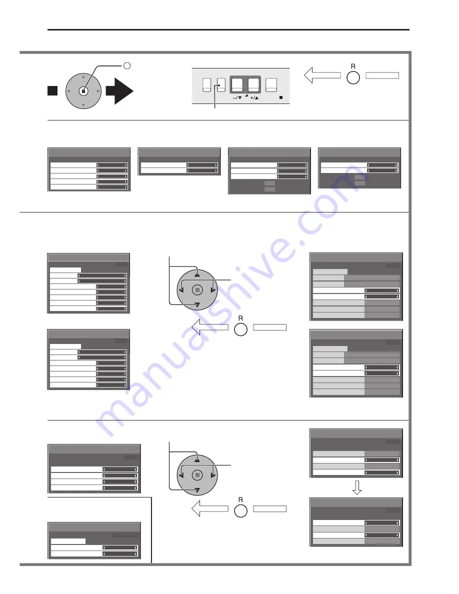
  Press to access 

each adjust 
screen.

Press the R button to return to 
previous menu screen.

Press to return to next menu screen.

To Signal screen for AV
(S Video) (see page 31, 32)

To Signal screen for 
Component (see page 32)

To Signal screen for RGB 
(see page 32, 33)

To Signal screen for Digital 
(see page 32, 33)

Note : 

“Signal” setup menu displays different setting condition for each input signals. (see page 16)

Note: 

Menu that cannot be adjusted is grayout. Adjustable menu changes depending on signal, input and menu setting.

Press the R button to return 
to “Setup” menu.

Press to select POWER ON 
Time / POWER OFF Time.

Press to Set up 
POWER ON Time / 
POWER OFF Time.

To Set up Timer selection 
screen (see page 25, 26)

To PRESENT TIME Setup 
(see page 25)

Press the R button to return 
to “Setup” menu.

Press to Setup.

Press to select Start Time / Finish Time 
(When Time Designation is selected).
Press to select Periodic Time / Operating Time 
(When Interval is selected).

To setup Screensaver 
(see page 27-29)

On-Screen Menu Displays

Summary of Contents for TH-37PR10B

Page 1: ...e instructions before operating your set and retain them for future reference Model No Operating Instructions High Definition Hospitality Plasma Display English The illustration shown is an image TH 37PR10B TH 42PR10B ...

Page 2: ... Advanced PIP 20 Picture Adjustments 21 Advanced settings 22 Sound Adjustment 23 Mute 23 Digital Zoom 24 PRESENT TIME Setup Set up TIMER 25 PRESENT TIME Setup 25 Set up TIMER 26 Screensaver For preventing image retention 27 Setup of Screensaver Time 28 Reduces screen image retention 28 Side Panel Adjustment 29 Reduces power consumption 30 Customizing the Input labels 30 Setup for Input Signals 31 ...

Page 3: ... in this plug Shall the fuse need to be replaced please ensure that the replacement fuse has a rating of 5 amps and that it is approved by ASTA or BSI to BS1362 Check for the ASTA mark ASA or the BSI mark on the body of the fuse If the plug contains a removable fuse cover you must ensure that it is refitted when the fuse is replaced If you lose the fuse cover the plug must not be used until a repl...

Page 4: ...unneeded small parts and other objects including packaging materials and plastic bags sheets to prevent them from being played with by young children creating the potential risk of suffocation Do not place the Plasma Display on sloped or unstable surfaces The Plasma Display may fall off or tip over Do not place any objects on top of the Plasma Display If water is spills onto the Plasma Display or ...

Page 5: ...ower supply plug with wet hands Doing so may cause electric shocks Do not do anything that may damage the power cable When disconnecting the power cable pull on the plug body not the cable Do not damage the cable make any modifications to it place heavy objects on top of it heat it place it near any hot objects twist it bend it excessively or pull it To do so may cause fire and electric shock If t...

Page 6: ...Cleaning and maintenance The front of the display panel has been specially treated Wipe the panel surface gently using only a cleaning cloth or a soft lint free cloth If the surface is particularly dirty wipe with a soft lint free cloth which has been soaked in pure water or water in which neutral detergent has been diluted 100 times and then wipe it evenly with a dry cloth of the same type until ...

Page 7: ...struction book Accessories Supply Check that you have the accessories and items shown The remote control is not included with this set Available for purchase separately Object model EUR7636090R I Year Guarantee Registration CRM Customer Relationship Management ...

Page 8: ...xing band To tighten To loosen Pull Pull Push the catch AC cord connection see page 11 AC cord fixing From EXTERNAL monitor terminal on Computer see page 9 From SERIAL Terminal on Computer see page 10 Optional Terminal Board Insert Slot covered Note Make sure that the AC cord is locked on both the left and right sides Push until the hook clicks 2 Pull off Unplug the AC cord UnplugtheACcordpressing...

Page 9: ...e Mini D sub 15P terminal The computer shown in the illustration is for example purposes only Additional equipment and cables shown are not supplied with this set Do not set the horizontal and vertical scanning frequencies for PC signals which are above or below the specified frequency range Component Input is possible with the pin 1 2 3 of the Mini D sub 15P Connector Change the Component RGB in ...

Page 10: ...es If multiple commands are transmitted be sure to wait for the response for the first command to come from this unit before sending the next command If an incorrect command is sent by mistake this unit will send an ER401 command back to the computer SL1A SL1B SL2A and SL2B of Command IMS are available only when a dual input terminal board is attached COMPUTER RS 232C Straight cable D sub 9p Start...

Page 11: ...ma Display is turned on setting condition is an example Press the button on the remote control to turn the Plasma Display off Power Indicator Red standby Press the button on the remote control to turn the Plasma Display on Power Indicator Green Turn the power to the Plasma Display off by pressing the switch on the unit when the Plasma Display is on or in standby mode Note During operation of the p...

Page 12: ...and PC selection see page 16 MENU Screen ON OFF This button is locked by initial setting Each time the MENU button is pressed the menu screen will switch see page 14 Volume Adjustment Volume Up Down When the menu screen is displayed press to move the cursor up press to move the cursor down see page 14 Enter Aspect button This button is locked by initial setting see page 14 17 N button see page 18 ...

Page 13: ...lution to image retention Channel Adjustment You can use this button when U V Tuner Board with Hospitality Port is installed optional accessories Refer to each Board s Operating Instruction for detail Volume Adjustment Press the Volume Up or Down button to increase or decrease the sound volume level OFF TIMER button The Plasma Display can be preset to switch to stand by after a fixed period The se...

Page 14: ...Y Setup Set up TIMER PRESENT TIME Setup Advanced settings Normal Normalise 0 0 2 2 Off 1 2 Black extension AGC Gamma Input level Advanced settings 0 0 0 0 0 0 2 2 W B Low B W B High R W B Low R W B Low G W B High G W B High B MENU ENTER INPUT VOL MENU ENTER INPUT VOL 1 2 To Pos Size adjust menu see page 18 During RGB PC input signal During AV S Video Component and Digital input signal To Advanced ...

Page 15: ... Side panel Wobbling Peak limit Finish Time Start Time White bar scroll Time Designation 6 15 12 30 High Off Off PRESENT TIME 15 00 Screensaver Start Function Mode Side panel Wobbling Peak limit Operating Time Periodic Time White bar scroll Interval 12 00 3 00 High Off Off PRESENT TIME 15 00 MENU ENTER INPUT VOL 2 Press to access each adjust screen Press the R button to return to previous menu scr...

Page 16: ...ch the signals from the source connected to the component RGB input terminals see page 31 In 2 screen display the same input mode cannot be selected for the main picture and sub picture Select the input signals to be connected by installing the optional Terminal Boards Press to select the input signal to be played back from the equipment which has been connected to the Plasma Display Input signals...

Page 17: ... size to change unexpectedly When viewing such programs it is recommended that theASPECT be set to 4 3 If adjusting the Picture V Pos V Size in Panasonic Auto with 16 9 mode the adjustment is not memorized When exiting the mode the screen will return to a former adjustment Panasonic Auto can not be selected while BNC Dual Video Terminal Board TY FB9BD is installed For an elongated image Image is e...

Page 18: ... picture position will shift up or down This picture position movement cannot be controlled by the Picture Pos Size function If adjusting the Picture V Pos V Size in Panasonic Auto with 16 9 mode the adjustment is not memorized When exiting the mode the screen will return to a former adjustment During RGB PC input signal During AV S Video Component and Digital input signal H Pos Adjust the horizon...

Page 19: ...ress to move the sub picture Each time the location of the sub picture will be moved Notes This button is effective only in the picture in picture The sub picture may be hidden by the on screen display depending on its position Press to change input signal Notes If Input lock in Options menu is set to other than Off MULTI PIP function isn t available Sound output is from the picture which is selec...

Page 20: ...ted in Audio Out PIP See page 23 In 2 screen display the same input mode cannot be selected for the main picture and sub picture The main picture and sub picture are processed by different circuits resulting in a slight difference in the clarity of the pictures There may also be a difference in the picture quality of the sub picture depending on the type of signals displayed on the main picture an...

Page 21: ...ts This menu selects the normal levels of Brightness and Contrast Dynamic For viewing in brighter environments This menu selects higher than normal levels of Brightness and Contrast Cinema Ideal for movies Note If you would like to change the picture and colour of the selected Picture menu to something else adjust using the items in the Picture menu see next page Colour Management On Enables vivid...

Page 22: ... only during AV S Video input signal In Contrast there is not a noticeable change even when contrast is increased with a bright picture or reduced with a dark picture Advanced settings Item Effect Adjustments Contrast Less More Selects the proper brightness and density for the room Brightness Darker Brighter Adjusts for easier viewing of dark pictures such as night scenes and black hair Colour Les...

Page 23: ...d Adjusts normal sounds Treble Adjusts high pitch sounds Balance Adjusts left and right volumes Surround Select On or Off Musical note is displayed on right side of the audio output screen label Selects PIP frame sound Selects main picture sound When PIP frame sound is chosen When main picture sound is chosen Attenuates human voice While the Sound menu is displayed if either the N button on the re...

Page 24: ...d for the enlarged display Each time this is pressed the magnification factor changes This is shown in the image being displayed Return to normal display quit Digital Zoom Press to exit from the Digital Zoom The cursor will move Notes When power goes OFF including Off Timer operation Digital Zoom terminates The Digital Zoom function cannot be selected while in the following operation state Multi v...

Page 25: ... ON Time POWER OFF Time Press to display the Setup menu Press to select Set up TIMER or PRESENT TIME Setup Press to display the Set up TIMER screen or PRESENT TIME Setup screen 1 2 Display the PRESENT TIME Setup screen To setup DAY and PRESENT TIME follow the procedure described below PRESENT TIME Setup 1 2 Press to select DAY or PRESENT TIME Press to setup DAY or PRESENT TIME button Forward butto...

Page 26: ...MER Press to select POWER ON Time POWER OFF Time Press to setup POWER ON Time POWER OFF Time button Forward button Back Notes Pressing or button once changes POWER ON Time POWER OFF Time 1minute Pressing or button continuously changes POWER ON Time POWER OFF Time by 15 minutes Press to select POWER ON Function POWER OFF Function Press to select On Press twice to exit from Setup Note Timer function...

Page 27: ...ould be used Reversal Scroll selection 2 3 1 4 Press to display the Setup menu Press to select Screensaver Press to display Screensaver screen Press to select Function Press to select the desired function White bar scroll Image Reversal White bar scroll The white bar will scroll from left to right Image Reversal Negative image will be displayed on the screen Mode selection Start setting 5 When the...

Page 28: ...e White bar scroll Off 6 15 12 30 High Off Off PRESENT TIME 99 99 Screensaver For preventing image retention Setup of Screensaver Time After selecting Time Designation or Interval the relevant Time Setup will become available for selection and the Operating Time may be set Time cannot be set when Mode is On or Off Press to select Start Time Finish Time When Time Designation is selected Press to se...

Page 29: ...remain on the side panels either side of the display field To reduce the risk of such an image retention illuminate the side panels Display the Screensaver screen Refer to the previous page operation guide steps 1 and 2 Notes To reduce the occurrence of image retention set the Side panel to High The side panels may flash alternate black white depending on the picture being shown on the screen Usin...

Page 30: ...is no signal When this is set to On the power supply of the unit goes Off 10 minutes after the input signals stop This function is effective for input signals except input from PC Mini D sub terminal Press to select Input label Press to change the Input label Customizing the Input labels This function can change the label of the Input signal to be displayed Select the input signal which you would ...

Page 31: ...match the signals from the source connected to the Component RGB input terminals Y PB PR signals Component R G B HD VD signals RGB 1 2 Press to display the Setup menu Press to select the Component RGB in select Press to select the desired input signal Component RGB Press to exit from adjust mode 3D Y C Filter For NTSC AV images Select Signal from the Setup menu duringAV S Video input signal Signal...

Page 32: ... occur set the system to match the format of the input signal Cinema reality P NR Press to select Cinema reality or P NR Press to set On Off Press to exit from adjust mode Cinema reality When on the display attempts to reproduce a more natural interpretation of sources such as movie pictures which are recorded at 24 frames per second If the picture is not stable turn the setting to off Note When O...

Page 33: ...that the input is set to RGB input this setting is valid only for RGB input signal Auto The H and V sync or synchronized signal are automatically selected If both input it is selected the H and V sync on G Uses a synchronized signal on the Video G signal which is input from the G connector VBS Uses a synchronized signal of Composite Sync input which is input from the HD connector Displays the H Ho...

Page 34: ... Off Hides all the items above from view Initial INPUT Off PC INPUT1 INPUT2 INPUT3 Adjusts the input signal when the unit is turned on Notes Only the adjusted signal is displayed see page 16 Signal can be displayed when the Terminal board is installed This menu is available only when INPUT lock is Off When a dual input terminal board is attached A or B is displayed depending on the selected input ...

Page 35: ... Only the adjusted signal is displayed see page 16 Signal can be displayed when the Terminal board is installed Input switch can be used when this is set to Off In two screen display mode if anything other than Off is set the value will be fixed as the value input in the single screen display mode When a dual input terminal board is attached A or B is displayed depending on the selected input sign...

Page 36: ...ID Control Off Disables external control by the ID On Enables the external control by the ID Display size Off On Adjusts the image display size on screen Off Sets the normal image display size on screen On Sets the image display size approximately 95 of the normal image display Off On Notes This setting is valid only when the input signals are as follows NTSC PAL SECAM M NTSC PAL60 PAL M PAL N BNC...

Page 37: ...On Note This mode is unavailable Rotate Off On Off Does not rotate the image On Rotates the image 180 degrees Serial Slot Select Slot1 Slot2 Slot3 Selects the slot which communicates serial Note The setting of an external command can be set only from the fixed serial terminal see page 10 Normalization When both main unit buttons and remote control are disabled due to the Button lock Remocon User l...

Page 38: ... AVL 10 07 08 1 Program Program number You can set 7 day timer programming by setting time and command Note Before setting Weekly Command Timer set PRESENT TIME Setup see page 25 Press to select Function Press to select On Note When Function is set to On SET up TIMER see page 26 is unavailable and Interval Time Designation in Mode of Screensaver see page 27 cannot be selected 1 Press to select a d...

Page 39: ...ss to select a command number 6 Press to select Time Command Press to set each item Time Set the time to execute a command program Pressing or button once changes Time 1 minute Pressing or button continuously changes Time by 15 minutes Command Select a command to execute at the set time This unit has 64 commands to set see page 43 Notes Command is performed in order of execution time regardless of...

Page 40: ...nu Press to select OSD Language Press and hold till the SHIPPING menu is displayed Press to select YES Press to confirm from the unit 1 Press the MENU button till the Setup menu is displayed 2 Press the Volume Up or Down button to select OSD Language 3 Press and hold the ENTER button till the SHIPPING menu is displayed 4 Press the Volume Up or Down button to select YES 5 Press the ENTER button and...

Page 41: ... indicative of malfunctioning This Plasma Display uses special image processing Hence a slight time lag may occur between image and audio depending on the type of input signal However this is not a malfunction Plasma Display panel Symptoms Checks The screen darkens slightly whenbrightpictureswithminimal movements are shown The screen will darken slightly when photos still images of a computer or o...

Page 42: ...16 56 25 36 0 21 800 600 60 Hz 37 88 60 32 40 0 22 800 600 72 Hz 48 08 72 19 50 0 23 800 600 75 Hz 46 88 75 00 49 5 24 800 600 85 Hz 53 67 85 06 56 25 25 1 024 768 60 Hz 48 36 60 00 65 0 26 1 024 768 70 Hz 56 48 70 07 75 0 27 1 024 768 75 Hz 60 02 75 03 78 75 28 1 024 768 85 Hz 68 68 85 00 94 5 29 1 152 864 75 Hz 67 50 75 00 108 0 30 1 280 960 60 Hz 60 00 60 00 108 0 31 1 280 960 85 Hz 85 94 85 00...

Page 43: ...he location of the sub picture lower left 33 DWA PIN2 The location of the sub picture upper left 34 DWA PIN3 The location of the sub picture upper right 35 DWA PIP Dual Picture mode Picture in Picture 36 DWA POP Dual Picture mode Picture out Picture 37 DWA SWP Swap main picture and sub picture when PIP mode 38 DWA TWN Dual Picture mode Picture and Picture 39 IMS PC1 Input select PC1 Main Picture w...

Page 44: ...A XGA SXGA UXGA compressed Horizontal scanning frequency 15 110 kHz Vertical scanning frequency 48 120 Hz Connection terminals PC IN HIGH DENSITY MINI D SUB 15PIN Y or G with sync 1 0 Vp p 75 Ω Y or G without sync 0 7 Vp p 75 Ω B PB CB 0 7 Vp p 75 Ω R PR CR 0 7 Vp p 75 Ω HD VD 1 0 5 0 Vp p high impedance VBS use HD port with picture 1 0 Vp p high impedance without picture 0 3 Vp p high impedance A...

Page 45: ...45 Memo ...

Page 46: ...46 Memo ...

Page 47: ...47 Memo ...

Page 48: ...n 01344 476540 or customer care panasonic co uk for more details Information on Disposal for Users of Waste Electrical Electronic Equipment private households This symbol on the products and or accompanying documents means that used electrical and electronic products should not be mixed with general household waste For proper treatment recovery and recycling please take these products to designate...

Reviews: