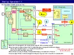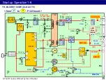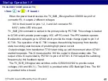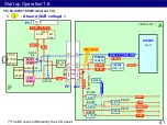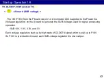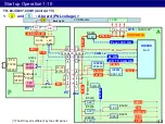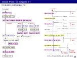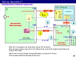
When the TV is plugged in, the rectifier start to produce DC voltage which leads
through PFC circuit directly to the power switches Q7351, Q7361. (PFC circuit
IC7201 does not operate at this moment.) Besides this DC voltage is provided also for
D7104, D7105 which provide start voltage to pin 1 of power supply IC 7301. When
the voltage on pin 1 rise up to predefined value IC7301 starts supplyinng of switching
pulses for Q7351, Q7361. Due to this current starts to lead through winding of T7301
which starts to generate output voltages. One of these voltages VCC is used for
power supplying of the IC 7301 to its pin 10
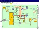
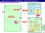
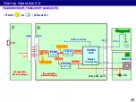
When the power supply starts up, the 16V is providing by D7421/C7423. This
voltage leads to IC7491, which is 5 volts DCDC converter.
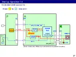
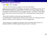
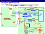
This voltage (STB5V) is provided to A board via connector P2 pin7. So if the TV is
plugged in, STB5V is provided to A board without trigger signal.
< from AC plug in to
: P board >
1
36
Start up Operation 1-3
TH- ##JX800*, 900W (Android TV)
Summary of Contents for TH-40JX700
Page 4: ...1 Lineup and Function Comparison 4 ...
Page 10: ...2 Function 10 ...
Page 18: ...3 Board Layout 18 ...
Page 23: ...23 4 Signal Flow and Troubleshoot of Picture Problem ...
Page 31: ...31 5 Start up Operation ...
Page 54: ...54 6 SOS Protection Circuit and Troubleshoot of Power Problem ...

