background image

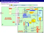
P

12V

PS-ON

BL-ON

PWM

A

A02

IC8000

SoC

LCD Module

T-CON

board

LCD Panel

1 - 5

BL_SOS

PS-ON

(Low=Normal)

Back

light

LED

Drive

BL-ON

PWM

116V(*)

60

10

12,16

11

13

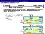
LED blinks

Detail error

Board may defect

1

BL_SOS (LED driver)

Panel / P

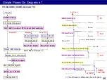
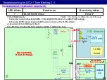
If the IC7800 detects

1.abnormal current of backlight LEDs ( = Backlight LED broken or Low(No) VLED voltage )
2.abnormal DC/DC power supply of LED+ (does not rise up the VLED voltage )

or abnormal of the LED Drive IC itself, 
the LED Drive IC output BL_SOS signal to IC8000 

LED blink 1 time.

(*)LED+ : The DC level is different by the LCD panel.

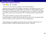
Troubleshooting for LED 1 Time Blinking 2-1

TX- ##JX800-83#*, TH-##JX700* (Android TV)

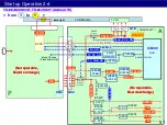
power  control

(No repairable,

Board exchange) 

(No repairable,

Board exchange) 

CN3

CN2

LED

LED-

(No repairable,

Board exchange) 

(No repairable,

Board exchange) 

Summary of Contents for TH-40JX700

Page 1: ...Panasonic Corporation 2021 Unauthorized copying and distribution is a violation of law c Model No LCD 202106 Order No ITD2106901GE 1 2021 LCD TV Android TV Ver 1 0 ...

Page 2: ...Revision History Version Issued Revised date Revised content Ver 1 0 7th Jun 2021 First version 2 ...

Page 3: ...ction 3 Board Layout 4 Signal Flow and Troubleshoot of Picture Problem 5 Start up Operation 6 SOS Protection Circuit and Troubleshoot of Power Problem Google Google Play YouTube Android TV Chromecast built in and other marks are trademarks of Google LLC ...

Page 4: ...1 Lineup and Function Comparison 4 ...

Page 5: ...icator Y N Web Browser Y N you can install from some Apps from Google play store IP Home Control Y N Works with Google Assistant Alexa Y except R Only Google Assistant Home Network Y Server Client N Swipe Share Y N TV Anywhere Y 2 N In House TV Streaming Y Client except B N USB HDD recording Y except R Y Mirroring Y Y iOS only Chromecast supported App 5 Lineup and Comparison of the Functions Europ...

Page 6: ...IR Bluetooth only voice control IR Bluetooth HDMI terminal HDCP eARC Auto low latency mode 3 2 2 N Y 3 2 3 N Y HDAVI control Y N CEC only USB2 0 3 0 HX9 2 1 HX8 1 1 2 0 Common Interface 2 only HX904 1 1 Digital Audio Output Optical Y Y Component video input Y N 6 Lineup and Comparison of the Functions Europe 2 The detail lineup and specification are different in each countries ...

Page 7: ... W N Media Player Y 2 0 Y Power LED Indicator Y N Web Browser Y N you can install from some Apps from Google play store IP Home Control Y only U Z N Works with Google Assistant Alexa Y Only Google Assistant Home Network Y Server Client N Swipe Share Y N TV Anytime Y 2 except W N USB HDD recording Y Except D L Y Mirroring Y Y iOS only Chromecast supported App 7 Lineup and Comparison of the Function...

Page 8: ...N Remote Controller IR Bluetooth only voice control IR Bluetooth HDMI terminal HDCP eARC Auto low latency mode 3 2 2 N Y 3 2 3 N Y HDAVI control Viera Link Y N USB2 0 3 0 2 1 2 0 Digital Audio out Optical Y Y Component video input Y N 8 Lineup and Comparison of the Functions Oceania Asia Middle East 2 The detail lineup and specification are different in each countries ...

Page 9: ...ice Preference About System update Note Android TV model After doing step power off by remote AC plug off AC plug in the screen is black and the Power LED is blinking orange about 30 sec The remote control don t work during this duration This is specification You can power on by remote after the Power LED turns red on 9 ...

Page 10: ...2 Function 10 ...

Page 11: ...y You can get quick access to your favorite content and easily find what you re looking for Customize Android TV to be your personal TV by pinning your favorite apps to the top rows Configure the Play Next channel to discover new content based on your preferences Customize your Home Screen Pin your favorite apps to the top row so your favorite shows are front and center Configure the Play Next cha...

Page 12: ...e Customer can assign favorite apps by MY App key on top of pre assign Apps Launcher Settings Picture Viewing Mode Sound Edit Although it is an Android TV it uses the Panasonic original UI The UI design allows customers to start the app without disturbing the viewing screen They can choose frequently used apps for easy access my Home Screen Design App Launcher Home Screen with Panasonic Original U...

Page 13: ... with ESPN NFL and ABC Not enough Explore the Apps games on offer Synchronize your preference Access Android TV with Google Account so that all your preferences and content will be synced A Google Account makes getting up and running really simple When a user logs in to their Android TV they get instant access to all their Downloaded apps YouTube preferences Music downloads Applications and Google...

Page 14: ...oogle Assistant will give you the answers on screen so you don t have to pick up another device Use your voice to jump to show control devices And more with Google Assistant Not Only Entertainment Also An Assistant It helps to get weather forecast and traffic condition base on the plan of the day What s on my agenda Users can Find out what s planned for their day Get the weather forecast Check the...

Page 15: ...erature Lock the door And many other etc Your Voice Become Your Controller Change volume open and closes app and even turn the power off can be done by your voice Users can Change the volume Open and close apps Turn the power off etc Google Assistant Voice Control and Connect with Other Home Devices 15 Google Assistant is not available in certain languages and countries Requires internet connectio...

Page 16: ...nd other content up to the big screen And best of all casting works with both Android and iOS devices iOS works with only supported Apps Easily cast your favorite movies music and more to your TV with Chromecast built in Chromecast built in is registered trademark of Google LLC Chromecast built inTM 16 ...

Page 17: ...e with Bluetooth device may result in connection interruptions If your wireless router supports 5GHz band try using the 5GHz band Or try using the wired LAN connection With Bluetooth Audio Link you can easily connect your TV to a wireless speaker or headphones to give you more listening choices ...

Page 18: ...3 Board Layout 18 ...

Page 19: ...Board Layout 1 19 No repairable A No repairable IR No repairable P No repairable K E y A K P TX 40 50 58 65JX800 83 Android TV TH 40 50 58 65JX700 Android TV TH 43 49 55 65JX800 900W Android TV G K ...

Page 20: ... K GK T CON Bluetooth ANT P3 P2 P5 GK5 A02 A16 A10B A12 JK8700 K10 Board Name Function A Board Main Board P Board Power supply Backlight Drive Board Name Function K Board Remote Receiver Power LED GK Board Power key Control key 20 TH 43 49 55 65JX800 900W Android TV ...

Page 21: ...8700 to A10 to A12 CN1 CNK1 Rear cover TOP BOTTOM RIGHT side LEFT side LEFT side RIGHT side TOP BOTTOM Board Function A Board Main Board P Board Power supply Backlight Drive IR unit Remote Receiver Power LED Keypad unit Power key Control key 21 TX 40 50 58 65JX800 83 Android TV TH 40 50 58 65JX700 Android TV CN3 CN2 ...

Page 22: ... are fixed to the panel Be careful about the damage of A board connector and the wires between A board and K GK Speaker when opening back cover Rear Cover Disassemble Assemble 22 Rear cover Panel Connector of A board Left picture is opened in this direction TX 40 50 58 65JX800 83 Android TV TH 40 50 58 65JX700 Android TV ...

Page 23: ...23 4 Signal Flow and Troubleshoot of Picture Problem ...

Page 24: ...e different by the models or countries 24 Video Audio Signal Process LAN CI slot only Europe USB2 HDMI1 2 3 to LCD Panel IC3800 Audio AMP TUNER Antenna terminal Head phone WiFi Bluetooth IC8000 Resize IP conv OSD IC3201 HP Driver USB1 ...

Page 25: ...enu Device Preferences About TV Self Test The test pattern and test sound are created by the main IC on the A board Yes No 1 Antenna level low 2 Connection mistake 3 Input devices NG 4 Input select mistake TV unit defective A board Panel or Speaker Troubleshoot for Picture Sound Problem 25 A IC8000 Peaks MTK Resize IP conv LCD Panel LCD OLED Panel Module T CON Test Pattern ...

Page 26: ...nce Press 4 keys continuously How to exit Switch off the TV unit The test pattern is created by the circuit in LCD Panel Module T CON board Troubleshoot for Picture Problem 1 26 2 patterns are automatically changed Android models are different procedure from previous models The Power LED will Blink during this mode TH 43 49 55 65JX800 900W Android TV TX 40 50 58 65JX800 83 TH 40 50 58 65JX700 Andr...

Page 27: ...rd Confirm Clean the flat cable connection between A board and T CON board of LCD Panel Flat cable Abnormal picture Bar line dot Unevenness Noise A A A A A A Color abnormal v line h line Dot or mura many lines If the picture is no problem A board must be defective If the picture is also abnormal LCD panel module must be defective Just in case confirm the flat cable connection between A board and T...

Page 28: ... by USB memory is not supported Menu Settings Device Preference About System update Software version 1 3 202 Status1 A Power on period A 100hrs B 200hrs C 200hrs 00006 Power on time hours max 65535 in decimal 0000020 Display on counter max 1048575 in decimal Status2 0 SOS history Latest 0 SOS history last time 0 SOS history last but one 0 SOS history 2nd time after shipping 0 SOS history 1st time ...

Page 29: ...times Do not keep pressing the Volume button just press once Press each key within 1 sec LCD Panel Test Mode While pressing Volume button of the main unit press Yellow button of the remote control 3 times for about more than 2 seconds press slowly While pressing Volume button of the main unit press Yellow button of the remote control 3 times Only GZ series special pattern is displayed when press O...

Page 30: ...nu will disappear during Hotel Mode Vol AV Input x3 Vol AV Input x3 Press Volume button of the main unit then press AV INPUT button of the remote control 3 times Do not keep pressing the Volume button just press once Press each key interval within 1 sec The message Hotel mode settings in process will appear at the top of the screen The Hotel mode settings menu will appear at the right side Set Sta...

Page 31: ...31 5 Start up Operation ...

Page 32: ...is black and the Power LED is blinking orange about 30 sec The remote control don t work during this duration This is specification You can power on by remote after the Power LED turns red on 32 TX 40 50 58 65JX800 83 Android TV TH 40 50 58 65JX700 Android TV TH 43 49 55 65JX800 900W Android TV ...

Page 33: ...rd LCD Panel STB3 3V F15V PNL12V A16 44 51 12V 3 3V 5V 1 8V 1 0V 3 3V PNL12V The DC level is different by the LCD panel 33 A02 Voltage Distribution 1 TH JX800 900W Android TV VLED ex 110V 1 8 10 13 16V STB5V 7 5 Up convert 1 4 STB1 5V GK POWER Switch TH JX800 900W Android TV 1 5V ...

Page 34: ...5V for standby voltage When the power supply receives the TV_SUB_ON signal it outputs 2 different voltages 16V to the A board on pins 1 2 3 and 4 of connector P2 64V to the LED backlight drive part After A board is ready to display it outputs Backlight_on command to P board P board output 110V to the backlight of LCD panel on pins 10 11 12 and 13 of connecter P3 10 POWER_ON KEY3 6 light 2 ex 64V 3...

Page 35: ...HO LO FB 64V Q7805 06 7 P2 D7102 03 Rectifier T7201 D7251 C7255 VCC Q7421 22 D7421 C7423 Through OFF OFF from AC plug in to P board 1 PFC IC7201 7 1 4 35 OFF PFC OFF AC100V 140V AC240V 330V Start up Operation 1 2 D7431 C7433 PFS LED Drive IC7800 P3 Anode Cathode8 Tr Tr 10 13 1 8 SRV 5V Cathode1 14 12 13 16 TH JX800 900W Android TV ...

Page 36: ...supplyinng of switching pulses for Q7351 Q7361 Due to this current starts to lead through winding of T7301 which starts to generate output voltages One of these voltages VCC is used for power supplying of the IC 7301 to its pin 10 When the power supply starts up the 16V is providing by D7421 C7423 This voltage leads to IC7491 which is 5 volts DCDC converter This voltage STB5V is provided to A boar...

Page 37: ... 7 G R_LED_on POWER Switch 10 37 Each models are different pin allocation but operation is same STB3 3V LCD_TV_SUB_ON IC8000 SoC Signal Processing 9 2 from to A board 1 Start up Operation 1 4 IC8202 STB1 5V IC5290 STB3 3V 5 9 13 3 7 1 2 1 2 TH JX800 900W Android TV SRV STB5V ...

Page 38: ...and the power LED on the K board through connector A10B K10 When the Power Switch on the key3 signal is grounded 1 The IC8000 lights on the RED LED and is ready to power on the TV by receiving the Power switch on Remote on Viera Link and so on This is a standby state When the power on command from the power switch the remote control and so on is provided to IC8000 IC8000 first outputs the TV_SUB_O...

Page 39: ...7201 8 7 VCC 1 4 BL ON L7851 39 Vcc PFC ON AC100V 380V AC240V 380V SRV 16V SRV VLED SRV 5V The DC level is different by the LCD panel Q7851 3 STB PWM 9 PFS Start up Operation 1 6 from to P LD board 2 3 LED Drive IC7800 P Q7404 Q7302 D7104 05 R7104 05 D7102 03 Rectifier D7251 C7255 D7431 C7433 Q7805 06 Q7421 22 D7421 C7423 Anode Cathode8 Tr Tr 10 13 1 8 Cathode1 Q7804 14 12 13 16 TH JX800 900W Andr...

Page 40: ... changes the switching frequency from standby state to working state because of providing high power current Output voltages from transformer T7301 start rising up until the moment when IC7401 started to operate This IC measures the 16V line output in the secondary side The output of this IC is provided by PC7301 to pin 4 of IC7301 IC7301 adjust the switching frequency by this feedback signal The ...

Page 41: ...el 10 13 P3 IC7800 DCDC LED Drive 64V Output A board SUB voltage 3 Start up Operation 1 8 16V 13 1 2 3 4 3 3V 0 95V IC8201 1 0V F16V IC8200 1 0V SUB3 3V 0 95V DCDCEN SUB5V F16V IC8000 SoC STB1 5V IC5200 IC8202 STB1 5V IC5290 STB3 3V 5 0V IC5220 STB3 3V LCD_TV_SUB_ON 7 5 STB5V TNPH1229 64V VLED 110V 1 8V IC5240 1 8V IC5000 TH JX800 900W Android TV SRV 12V 16V ...

Page 42: ...generate the SUB Voltages used for signal processing operation SUB1 0V 1 8V 3 3V and 5V Each voltage regulators start up by high state of DCDCEN signal which is pull up to F16V So F16V is provided to A board each SUB voltage regulator ICs start output A board SUB voltage 3 42 Start up Operation 1 9 TH JX800 900W Android TV ...

Page 43: ...and A board PNL voltage 4 5 Start up Operation 1 10 14 64V Output 16V 1 2 3 4 13 5 11 10 1 2 3 4 3 3V 1 0V F16V IC8200 SUB3 3V LCD_TV_SUB_ON Panel_VCC_ON A16 44 51 BL_ON PNL12V F15V SUB5V F16V IC8000 SoC STB5V BL_SOS IC5260 STB1 5V PWM1 2 IC5200 12V IC5290 STB3 3V 5 0V IC5220 STB3 3V TNPH1229 VLED 110V 12 13 16 SRV PNL12V 1 8V IC5240 1 8V 0 95V IC8201 0 95V 1 0V IC8202 STB1 5V DCDCEN IC5000 TH JX8...

Page 44: ...to the P board That command turns on the IC7800 for LED backlight drive Then the 64V rise up over 110V and output to the backlight on the LCD panel The backlight starts lighting by PWM signals and LCD panel displays the pictures If the backlight drive circuit does not work normally the BL_SOS signal is informed to the IC8000 At that time IC8000 stops outputting the TV_SUB_ON signal and blinks the ...

Page 45: ... 7 VCC 1 4 BL ON L7851 45 Vcc PFC ON AC100V 380V AC240V 380V SRV 16V SRV VLED SRV 5V The DC level is different by the LCD panel Q7851 3 STB PWM 9 PFS 14 P Q7404 Q7302 LED Drive IC7800 Start up Operation 1 12 P board backlight drive 6 D7104 05 R7104 05 D7102 03 Rectifier D7251 C7255 D7431 C7433 Q7805 06 Q7421 22 D7421 C7423 Anode Cathode8 Tr Tr 10 13 1 8 Cathode1 Q7804 12 13 16 110V P3 TH JX800 900...

Page 46: ...16V 64V Power LED off TV_SUB_OFF TV_SUB_OFF AC Plug in STB5V form P to A 16V from P to A PNL12V from A to Panel T CON SUB_ON from A to P Power LED Panel_Vcc_ON from A to Panel TCON VLED from P to Panel Backlight BL_ON EVDD_ON from A to P Standby Power on Standby Power on Power on Standby Power on 5V 16V 12V ex 64V VLED ex 110V 64V up to VLED BL_ON_ON signal Power LED Red The DC level is different ...

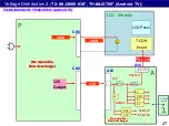
Page 47: ...V 1 0V 3 3V PNL12V 47 A02 Voltage Distribution 2 TX JX800 83 TH JX700 Android TV VLED 12V 1 5 1 5V STB1 5V POWER Switch VLED 5V STB5V TX JX800 83 TH JX700 Android TV No repairable Board exchange No repairable Board exchange CN2 CN3 No repairable Board exchange No repairable Board exchange ...

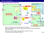
Page 48: ...board change from standby mode to high current mode After A board is ready to display it outputs Backlight_on command to P board P board output VLED to the backlight of LCD panel 6 light 2 48 Start up Operation 2 1 6 light VLED 13 10 1 5 12V Output POWER Switch POWER_ON 3 Mode Change Standby Normal TX JX800 83 TH JX700 Android TV No repairable Board exchange No repairable Board exchange CN2 CN3 No...

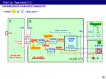
Page 49: ...1 Start up Operation 2 2 IC5290 STB3 3V IC8202 STB1 5V IC5280 STB5V 7 11 5 6 3 3V 3 12V STB1 5V STB3 3V STB12V STB5V 1 2 3 4 5 TX JX800 83 TH JX700 Android TV Power control No repairable Board exchange No repairable Board exchange SRV 12V 16V SRV STB5V CN2 No repairable Board exchange No repairable Board exchange ...

Page 50: ... the remote control receiver and the power LED on the Keypad board through connector A10 When the Power Switch on the key3 signal is grounded 1 The IC8000 lights on the RED LED and is ready to power on the TV by receiving the Power switch on Remote on Viera Link and so on This is a standby state When the power on command from the power switch the remote control and so on is provided to IC8000 IC80...

Page 51: ... IC5004 TV_PS_ON Panel_VCC_ON A16 44 51 PNL12V PNL 12V Q5200 BL_SOS TV_SUB_ON 10 11 12 16 IC5000 DCDC T CON Back Light Start up Operation 2 4 BL_ON PWM1 2 STB12V 1 0V STB1 5V STB3 3V IC8202 STB1 5V IC5290 STB3 3V STB5V Mode Change Standby Normal TX JX800 83 TH JX700 Android TV power control from to 3 6 No repairable Board exchange No repairable Board exchange No repairable Board exchange No repair...

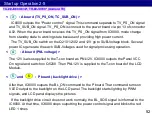
Page 52: ... the IC8000 At that time IC8000 stops outputting the power control signal and blinks the red LED 1 times and P board backlight drive 6 5 IC8000 outputs the Power control signal This command separate to TV_PS_ON signal and TV_SUB_ON signal TV_PS_ON is connect to the power board via pin 13 of connector A02 When the power board receives this TV_PS_ON signal from IC8000 mode change from standby state ...

Page 53: ...STB5V 3 3V in A PNL12V from A to Panel T CON PS_ON from A to P Power LED Panel_Vcc_ON from A to Panel TCON VLED from P to Panel Backlight BL_ON from A to P Standby Power on Power on Standby Power on 12V 5V 3 3V 12V VLED output BL_ON_ON signal Power LED Red The DC level is different by the LCD panel STB5V 3 3V output TV_SUB_ON signal STB12V F12V output SUB_ON in A TX JX800 83 TH JX700 Android TV ex...

Page 54: ...54 6 SOS Protection Circuit and Troubleshoot of Power Problem ...

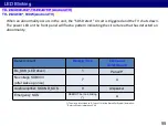
Page 55: ...cted an abnormality LED Blinking Detect content Blinking Time Estimated Defect Board BL_SOS LED driver 1 Panel P No voltage SUB3 3V after wake up once 7 A Audio amplifier SOUND_SOS 9 A speaker Emergency SOS REBOOT but no blinking A TH JX800 900W Android TV TX JX800 83 TH JX700 Android TV The history is recorded as D Hex of 13 at the Status2 of System Information Refer to System Information P 28 ...

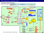
Page 56: ...tput Transformer T7301 PFC T7202 IC7201 DC DC IC7301 16V P3 16V BL_SOS BL_ON 9 14 LCD_TV_SUB_ON 15 Tr 44 51 64V 64V Output 1 2 3 4 13 10 11 1 2 3 4 IC7800 LED DC DC Drive Protection Circuit N SOS N SOS SOS Detect Circuit and Power Flow 1 F15V 1 8 10 13 VLED 110V Q7421 22 Q7805 06 1 8V IC5240 0 95V IC8201 SUB3 3V SUB5V 1 8V 0 95V 1 0V IC5000 7 5 STB5V DC DC IC7491 Over voltage protection Low Detect...

Page 57: ...inks Detail error Board may defect 1 BL_SOS LED driver Panel P If the IC7800 detects 1 abnormal current of backlight LEDs Backlight LED broken or Low No VLED voltage 2 abnormal DC DC power supply of IC7800 does not rise up the VLED voltage or the IC7800 does not work No Vcc or No BL_ON PWM signal or defect itself the IC7800 output BL_SOS signal to IC8000 LED blink 1 time VLED The DC level is diffe...

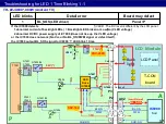
Page 58: ...e of them shorted NG OK over100V P board Connect P3 connector Power on Check if the voltage of SRV VLED pin10 13 of P3 before LED 1 blink All OK Panel Module Panel Module Shorted OK Short check Q7851 between Source and Drain P board Troubleshooting for LED 1 Time Blinking 1 2 P board TNPA6699 SRV VLED Q7851 S D G P3 TH JX800 900W Android TV ...

Page 59: ...16 44 51 PNL12V PNL 12V Q5200 TV_SUB_ON 10 11 IC5000 DCDC T CON Back Light BL_ON STB12V 1 0V SOS Detect Circuit and Power Flow 2 BL_SOS SOUND_SOS 9 Blink 1 Blink IC3800 AMP Protection Circuit TX JX800 83 TH JX700 Android TV No repairable Board exchange No repairable Board exchange Low voltage detect 7 Blink OFF power control RST Over voltage protection OFF Low Detect OFF No repairable Board exchan...

Page 60: ...cklight LED broken or Low No VLED voltage 2 abnormal DC DC power supply of LED does not rise up the VLED voltage or abnormal of the LED Drive IC itself the LED Drive IC output BL_SOS signal to IC8000 LED blink 1 time LED The DC level is different by the LCD panel Troubleshooting for LED 1 Time Blinking 2 1 TX JX800 83 TH JX700 Android TV power control No repairable Board exchange No repairable Boa...

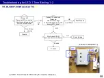
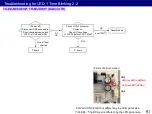
Page 61: ...of them shorted NG OK over100V P board Connect CN3 connector Power on Check if the voltage of VLED before LED 1 blink All OK Panel Module P board Troubleshooting for LED 1 Time Blinking 2 2 TX JX800 83 TH JX700 Android TV LED or LED1 LED2 LED or LED1 LED2 CN3 CN2 CN2 and CN3 location is different by the LCD panel size Picture of 40inch model ...

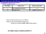
Page 62: ...d Flash IN THESE CASES A BOARD DEFECTS 62 Troubleshooting for LED Blinking 7 13 time blink 7 blinks is problem about the power line of SUB3 3V 13 blinks is problem about IC8000 and software issue mostly case the memory eMMC NAND Flash IC problem TH JX800 900W Android TV TX JX800 83 TH JX700 Android TV ...

Page 63: ...ks 9 times Remove A12 connecter Power on Does LED blinks again L R speaker wire of speaker A board A A02 IC8000 IC3800 AMP F16V SOUND_SOS 9 Blink A12 16V From P BOARD 63 Troubleshooting for LED Blinking 9 time blink 1 4 TH JX800 900W Android TV TX JX800 83 TH JX700 Android TV SRV 12V 16V A A02 IC8000 IC3800 AMP SOUND_SOS 9 Blink A12 12V From P BOARD 1 5 SRV 12V 16V Q2101 Q2102 TV_SUB_ON TH JX800 9...

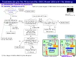
Page 64: ...Picture The voltage of VLED is different by the LCD panel Troubleshooting for No Picture and No OSD Power LED is lit No blinking Confirm Clean the flat cable connection from A16 to T CON board of LCD Panel LCD Module A 12V 1 2 3 4 5 A16 44 51 T CON Panel_VCC_ON Or sound check with TV mode No Picture Green LED power LED indicator setting On A02 LED blink If entering the test mode the Power LED will...

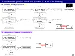
Page 65: ...Replace A board Disconnect A02 connecter Short check the SRV 16V In A board Shorted Replace P board OK 65 P A STB5V 16V P2 A02 Replace A board No Picture LED off even if the power LED indicator setting On TH JX800 900W Android TV TX JX800 83 TH JX700 Android TV NG Replace A board Check if the output of STB12V Just AC input Disconnect A02 connecter Short check of STB12V line in A board No Shorted S...

Page 66: ...copy from TV original A board to USB Memory Data copy from USB Memory to TV new A board Note 1 Depending on the failure of boards function does not work 2 This function can be effective among the same model numbers Before replacing A Board After replacing A Board 3 Input Password 2770 4 Copying maximum few minutes 5 Finish 6 Remove USB Memory from TV 7 Turn off the TV Note New folder user_setup wi...

Reviews: